
Brake lining for railway vehicles and disc brake equipped with the same

a technology for disc brakes and brake linings, which is applied in the direction of friction linings, mechanical devices, transportation and packaging, etc., can solve the problems of increasing the frictional surface temperature the brake disc that come into contact with each other, increasing the wear of the brake lining, and reducing the durability of the disc brake, so as to achieve the effect of stable coefficient of friction and enhanced durability and reliability

Active Publication Date: 2014-04-10
RAILWAY TECH RES INST +2
View PDF15 Cites 10 Cited by
  • Summary
  • Abstract
  • Description
  • Claims
  • Application Information

AI Technical Summary

Benefits of technology

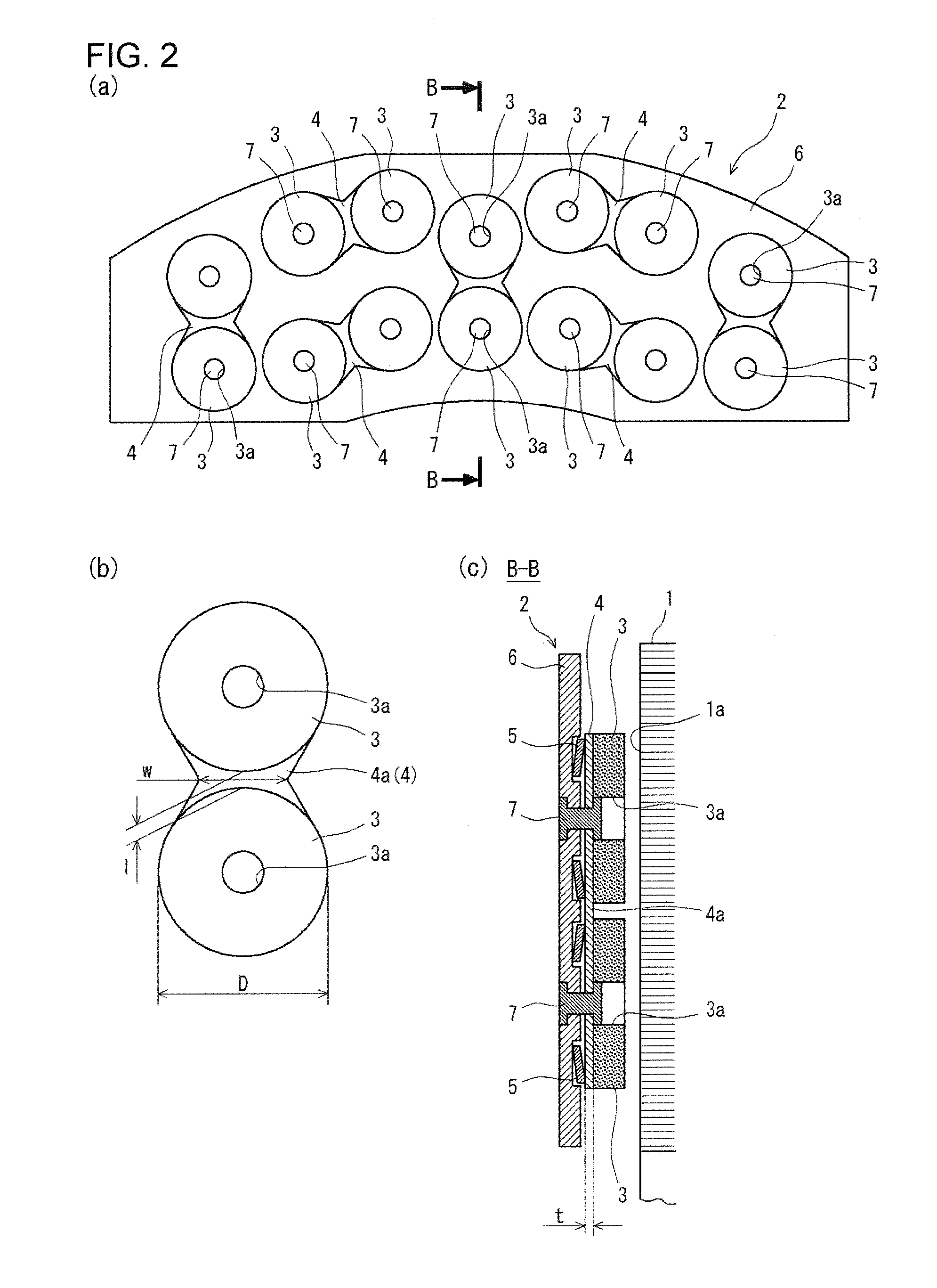
The brake lining and disc brake for railway vehicles described in this patent improve braking performance by ensuring even contact pressure between the brake lining and brake disc, resulting in a stable coefficient of friction. This is achieved through a configuration where friction members are paired and each pair is provided with a metallic backing and a spring member. The friction members are mounted to a base plate using rivets. This results in a more durable and reliable brake system.

Problems solved by technology

In addition, during the braking operation, the temperatures of the frictional surfaces of the brake lining and the brake disc that come into contact with each other increase due to frictional heat.
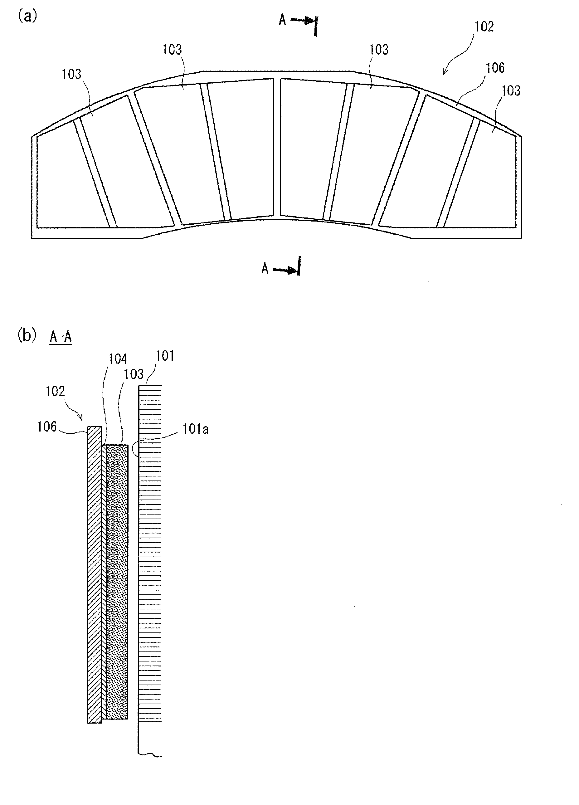
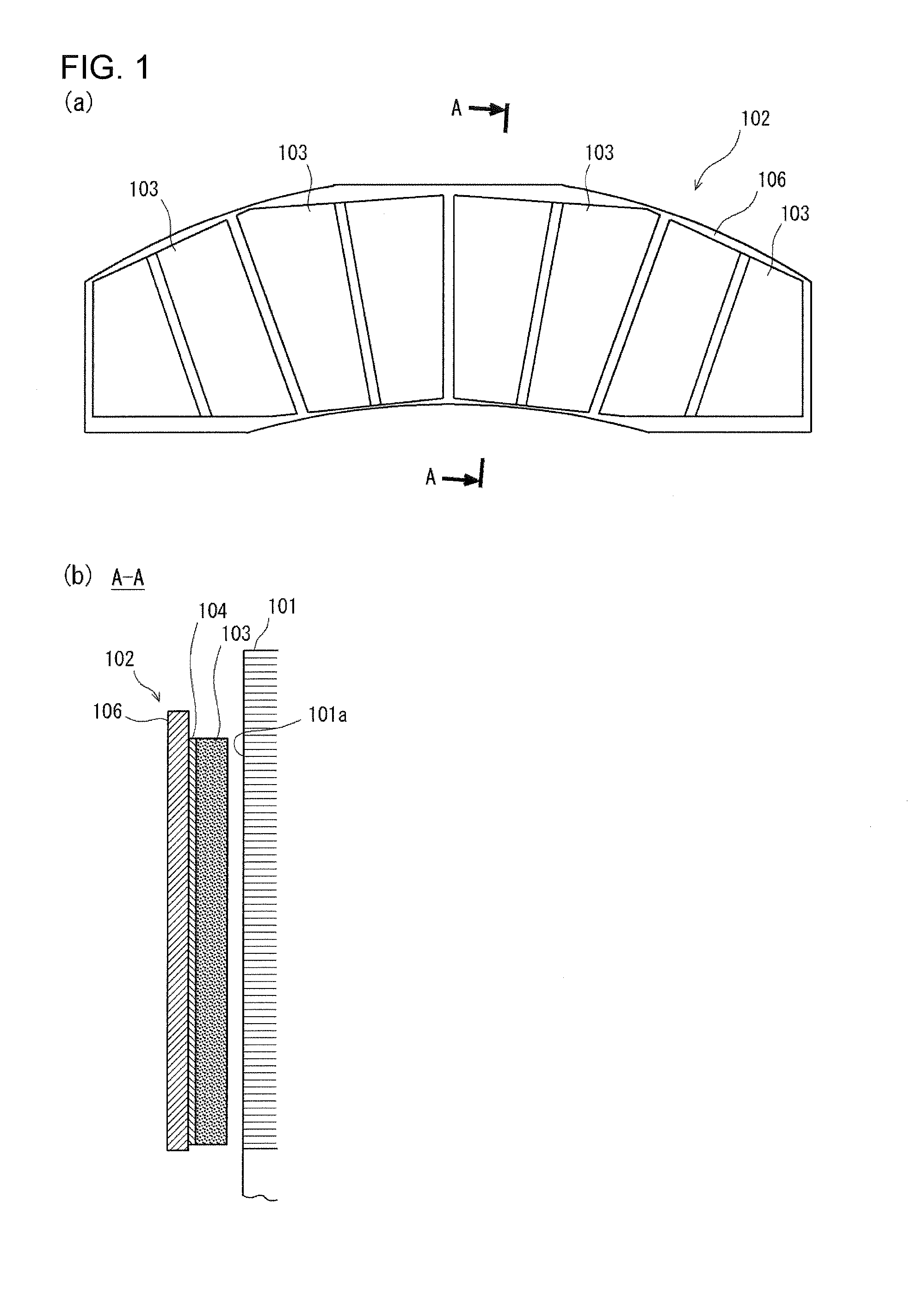
Consequently, the temperature increase due to the friction during the braking operation becomes locally excessive, which results in an increase in wear of the brake lining 102 (friction members 103) and the brake disc 101 or the formation of cracks in the brake disc 101 at the location experiencing the excessive temperature increase.
This thermal damage leads to the loss of durability of the disc brake.
If the coefficient of friction varies depending on the traveling speed at the time of start of the braking operation, accurate control of deceleration of the vehicle under braking becomes difficult, thus making it impossible to ensure the required braking performance.
In particular, in the case of high speed railway vehicles such as a Shinkansen “bullet train”, the variation in the coefficient of friction poses a problem because the traveling speed broadly ranges from low speed to high speed.
If such rotation of the friction members is repeated as a result of repeated braking operations, loosening occurs at the fastening portion between the friction members and the base plate, which finally results in falling off of the friction members.
Because of this, it is impossible to ensure sufficient durability and reliability.

Method used


Image

  • Brake lining for railway vehicles and disc brake equipped with the same
  • Brake lining for railway vehicles and disc brake equipped with the same
  • Brake lining for railway vehicles and disc brake equipped with the same

Examples


examples

[0054]To verify the advantageous effects of the present invention, Finite Element Method (FEM) analysis and brake tests were conducted as described below.

[Summary of the Analysis and Tests]

[0055]An FEM analysis was conducted to evaluate the uniformity of contact pressure between a brake lining and a brake disc during braking operation. In the analysis, the brake lining and the brake disc were modeled as elastic bodies, and a load corresponding to the pressing force by the brake caliper was applied from the back side of the brake lining. In this analysis, the loads acting on the individual friction members were evaluated.

[0056]Brake tests were conducted primarily to evaluate the stability of the coefficient of friction between the brake disc and the brake lining during braking operation. In the tests, a wheel to which the brake disc was mounted was caused to rotate at its position, and the brake lining mounted to the brake caliper was pressed against the brake disc for braking. In th...


PUM


Abstract

A disc brake for railway vehicles includes a brake disc fixed to a wheel or an axle of a railway vehicle and a brake lining configured to be pressed against a frictional surface of the brake disc by a brake caliper. The brake lining includes a plurality of friction members arranged to be spaced from each other, each of the friction members having a surface that faces the frictional surface of the brake disc, a metallic backing secured to back surfaces of the friction members, and a base plate supporting the friction members on the back surface side via spring members. The base plate is mounted to a brake caliper; wherein the friction members are provided in pairs with each pair being formed by two adjacent ones of the friction members, and the metallic backing is a one-piece member provided for each pair of the friction members.

Description

TECHNICAL FIELD[0001]The present invention relates to a disc brake for use as a braking device for railway vehicles, and in particular to a brake lining for railway vehicles configured to be pressed against a frictional surface of a brake disc fixed to a wheel or an axle thereof and a disc brake equipped with the brake lining.BACKGROUND ART[0002]As a braking device for land transportation vehicles such as railway vehicles, automobiles, and motorcycles, disc brakes have been widely used in recent years as those vehicles have become increasingly faster and larger. A disc brake is a device that produces a braking force by means of friction generated by sliding contact between a brake disc and a brake lining[0003]In the case of railway vehicles, a braking force is generated by pressing a brake lining, by a brake caliper, against a frictional surface of a brake disc in the form of a donut-shaped disc which has been mounted and fixed to the wheel or the axle. In this manner, the rotation ...

Claims


Application Information

Patent Timeline
Patent Type & Authority Applications(United States)
IPC IPC(8): F16D65/092F16D55/22
CPCF16D55/22F16D65/092B61H5/00F16D69/00
Inventor KATO, TAKANORIFUJIMOTO, TAKAHIROASABE, KAZUTAKASAKAGUCHI, ATSUSHIKARINO, YASUSHISAGA, SHIN-ICHIMAEJIMA, TAKASHINAKANO, SATORUNAKANO, TAKESHI
Owner RAILWAY TECH RES INST
Learn More