
Liquid crystal module package box

a liquid crystal module and package box technology, applied in the field of packaging, can solve the problems of affecting affecting the efficiency affecting the external forces of external forces, so as to prevent the damage of liquid crystal modules, reduce the cost of transportation, and protect liquid crystal modules.

Inactive Publication Date: 2014-04-10
SHENZHEN CHINA STAR OPTOELECTRONICS TECH CO LTD
View PDF3 Cites 15 Cited by
  • Summary
  • Abstract
  • Description
  • Claims
  • Application Information

AI Technical Summary

Benefits of technology

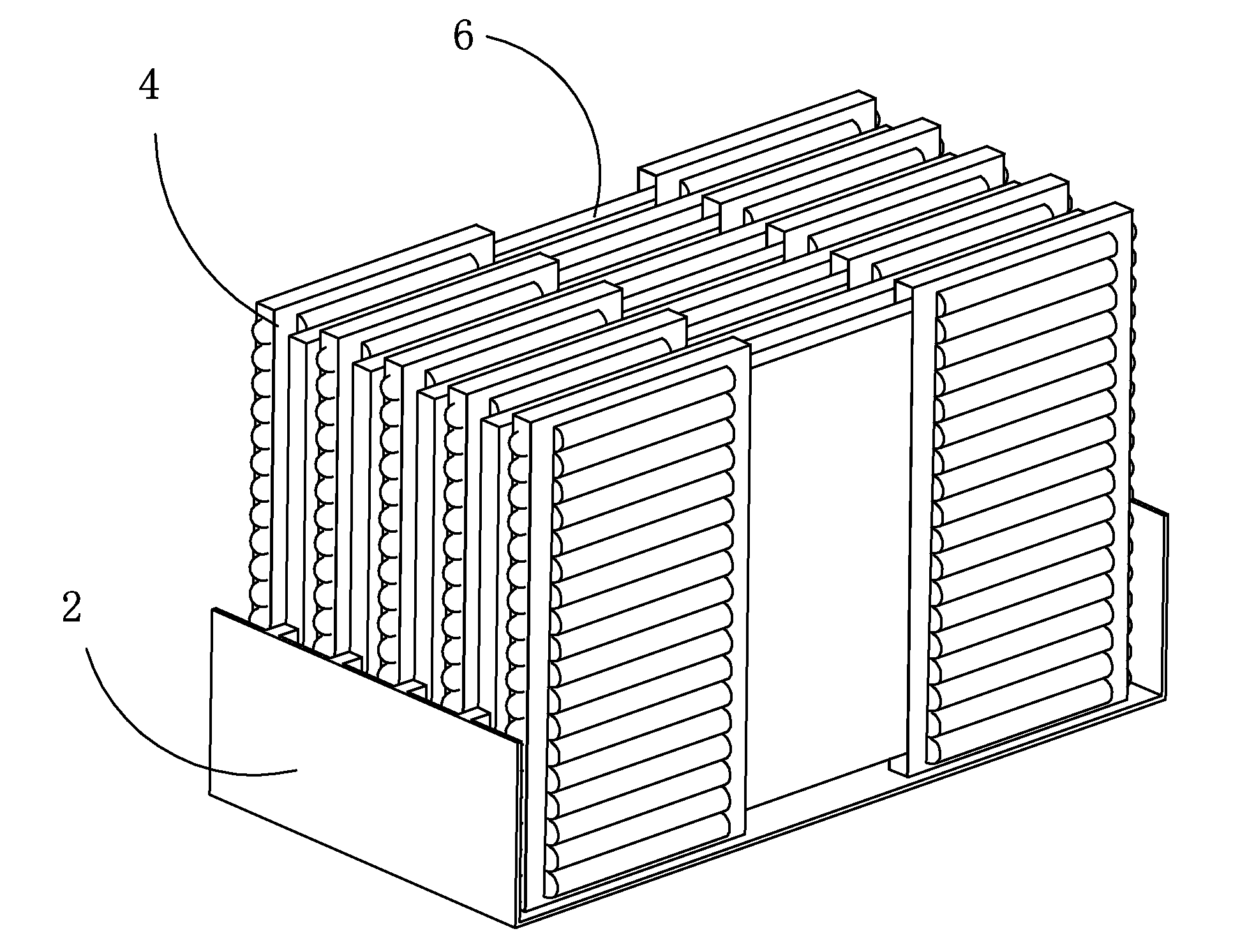
The present invention provides a liquid crystal module package box that uses air cushioning bags and retention racks to package liquid crystal modules for effective protection and prevention of damages caused by external forces. The package structure is simple, reduces space occupation rate, and effective reduction of transportation cost. The air-cushioning bags are alternately fit over the liquid crystal modules to provide a high utilization rate and lower down material cost, and the retention racks are provided with cushioning units to cushion the liquid crystal modules and eliminate height difference between adjacent ones of the liquid crystal modules so as to ensure flatness and further protect the liquid crystal modules.

Problems solved by technology

It is inevitable that a liquid crystal module may be impacted by external forces and falling during the shipping thereof.
Cushioning components made of these materials have a high space occupation rate, which affects the cost of transportation.
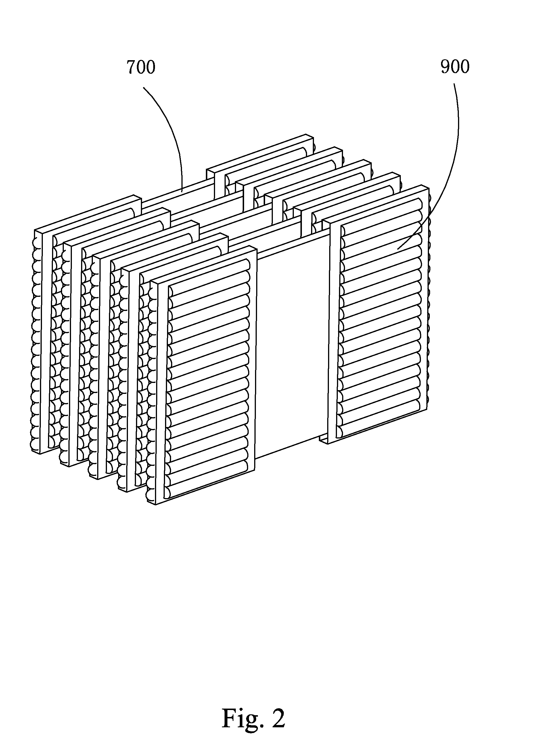
For packaging of plate-like products, if each plate is individually packaged and then deposited in a package box, then the amount used will be excessive (as shown in FIG. 2).
This results in a waste of the air column package 900 and also increases the overall thickness, which in turn reduces the amount of products to be shipped with a single box and thus increases the transportation cost.

Method used


Image

  • Liquid crystal module package box
  • Liquid crystal module package box
  • Liquid crystal module package box

Examples


Embodiment Construction

[0041]To further expound the technical solution adopted in the present invention and the advantages thereof, a detailed description is given to a preferred embodiment of the present invention and the attached drawings.

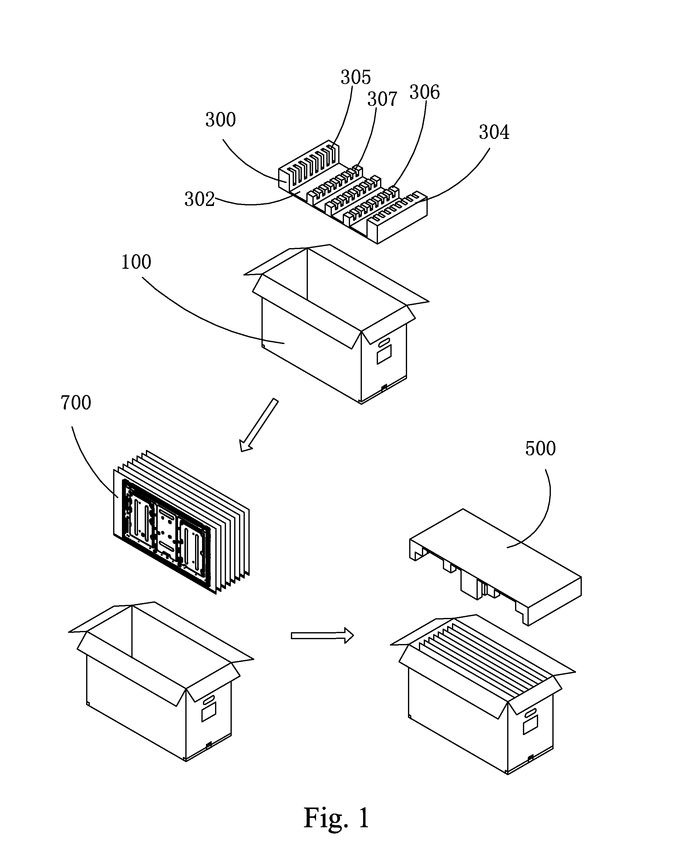
[0042]Referring to FIGS. 2-8, the present invention provides a liquid crystal module package box, which comprises a box body (not shown), two retention racks 2 that are arranged in the box body and opposite to each other, and a plurality of sets of air-cushioning bags 4. To package, liquid crystal modules 6 are positioned between the two retention racks 2 and the plurality of sets of air-cushioning bags 4 is alternately fit over the liquid crystal modules 6.

[0043]Each set of air-cushioning bags 4 comprises two bags that are respectively fit over two ends of a liquid crystal module 6.

[0044]The retention racks 2 each comprise a first fixing unit 22, a second fixing unit 24 connected to the first fixing unit 22, and a third fixing unit 26 connected to the second fixing un...


PUM


Abstract

A liquid crystal module package box includes a box body, two retention racks that are arranged in the box body and opposite to each other, and a plurality of sets of air-cushioning bags, whereby to package, liquid crystal modules are positioned between the two retention racks and the plurality of sets of air-cushioning bags is alternately fit over the liquid crystal modules. The liquid crystal module package box of the present invention uses retention racks and air-cushioning bags arranged inside the box body to effectively protect the liquid crystal modules so as to avoid damages of the liquid crystal modules caused by external forces. Further, the package structure is simple, where air-cushioning bags are alternately fit over the liquid crystal modules to provide a high utilization rate and lower down material cost. Further, the retention racks are provided with cushioning units to effectively cushion the liquid crystal modules.

Description

BACKGROUND OF THE INVENTION[0001]1. Field of the Invention[0002]The present invention relates to the field of packaging, and in particular to a liquid crystal module package box.[0003]2. The Related Arts[0004]In the field of manufacture of liquid crystal display devices, the manufacture of liquid crystal display devices includes a process of assembling, which assembles various components, including a liquid crystal module, a main control circuit, and an enclosure, together. These components are each manufactured in advance and packaged for being later assembled to form a complete liquid crystal display device. It is inevitable that a liquid crystal module may be impacted by external forces and falling during the shipping thereof. To well protect the liquid crystal module, it is desired to add a cushioning structure in a package box to spread acting forces induced by external forces and absorb the impact energy of falling.[0005]A conventional liquid crystal module package box is illu...

Claims


Application Information

Patent Timeline
IPC IPC(8): B65D81/05B65D81/113B65D85/48
CPCB65D81/052B65D81/113B65D85/48B65D25/107H01L21/67369
Inventor KUO, YICHENGCHEN, SHIHHSIANGYU, GANGCHENG, JIAHEZHAO, ZHILIN
Owner SHENZHEN CHINA STAR OPTOELECTRONICS TECH CO LTD
Learn More