Current-Monitoring Apparatus

a current monitoring and apparatus technology, applied in the direction of current measurements only, measurement devices, instruments, etc., can solve the problems of increasing the cost of using the circuit, reducing the lifetime of the circuit, and using the sense resistor, so as to reduce the current and power

Inactive Publication Date: 2014-04-10
AVAGO TECH INT SALES PTE LTD
View PDF11 Cites 6 Cited by
  • Summary
  • Abstract
  • Description
  • Claims
  • Application Information

AI Technical Summary

Benefits of technology

[0046]This aspect of the disclosure is particularly useful when applied to a power supply which has multiple switches, each having a locally positioned temperature sensor. Using a temperature sensor local to the switch, rather than a single general temperature sensor, allows continued operation of the remaining ‘cold’ switches and reduces the current and power only in the ‘hot’ switch.

Problems solved by technology

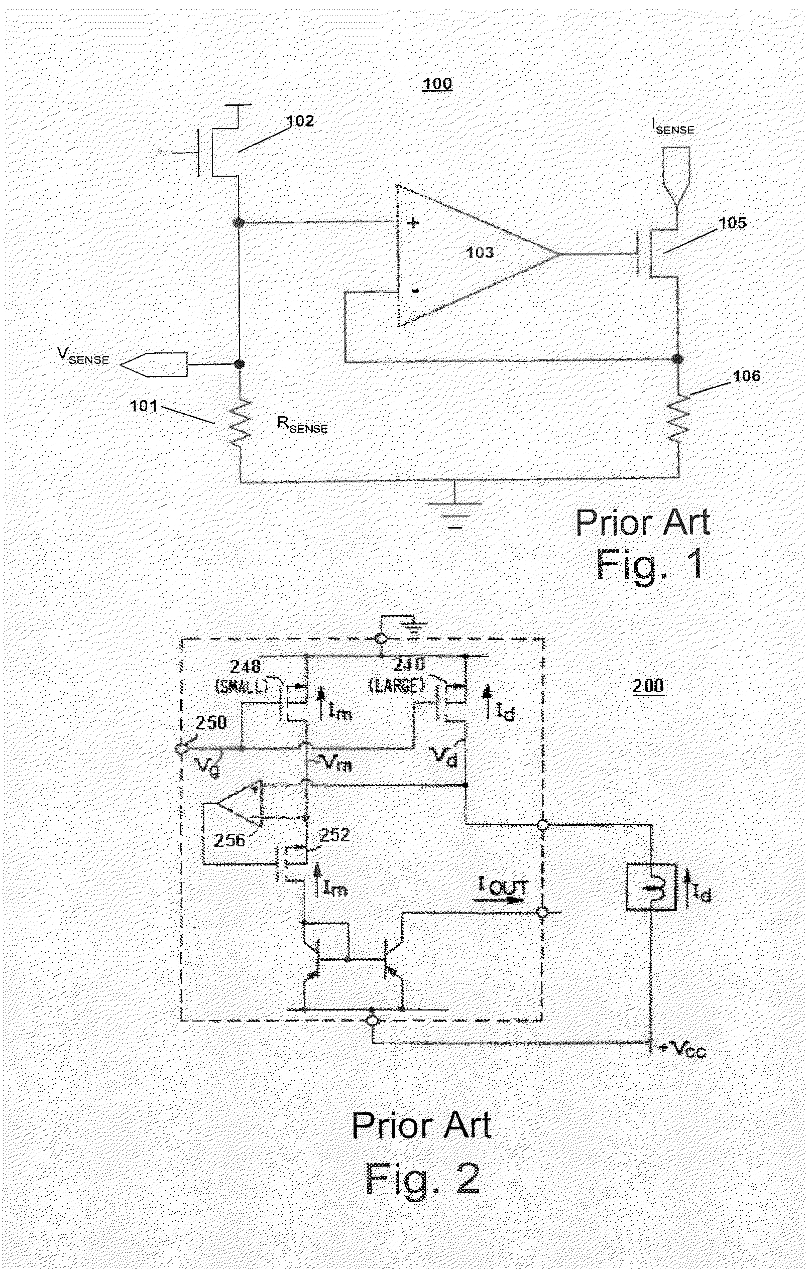
One difficulty with the conventional current sense circuit 100 is that it uses the sense resistor 101.
If the sense resistor 101 is large, the sense circuit 100 has high power dissipation, which increases the costs of using the circuit, potentially decreases its lifetime, and also can contribute to heat dissipation challenges.
One problem with the reliability of current sensing circuits, such as the one shown in U.S. Pat. No. 5,220,207, is that the circuits will inevitably include ‘implicit resistances’ which arise from metallization within a device, and in the leads to / from a device.
Such metallization resistance may be neglected in many cases.
However, as the currents rise, so do the Joule heating losses due to the implicit metallization resistances.
At some current levels, the mirroring function may break down, resulting in inaccurate current sense operation.
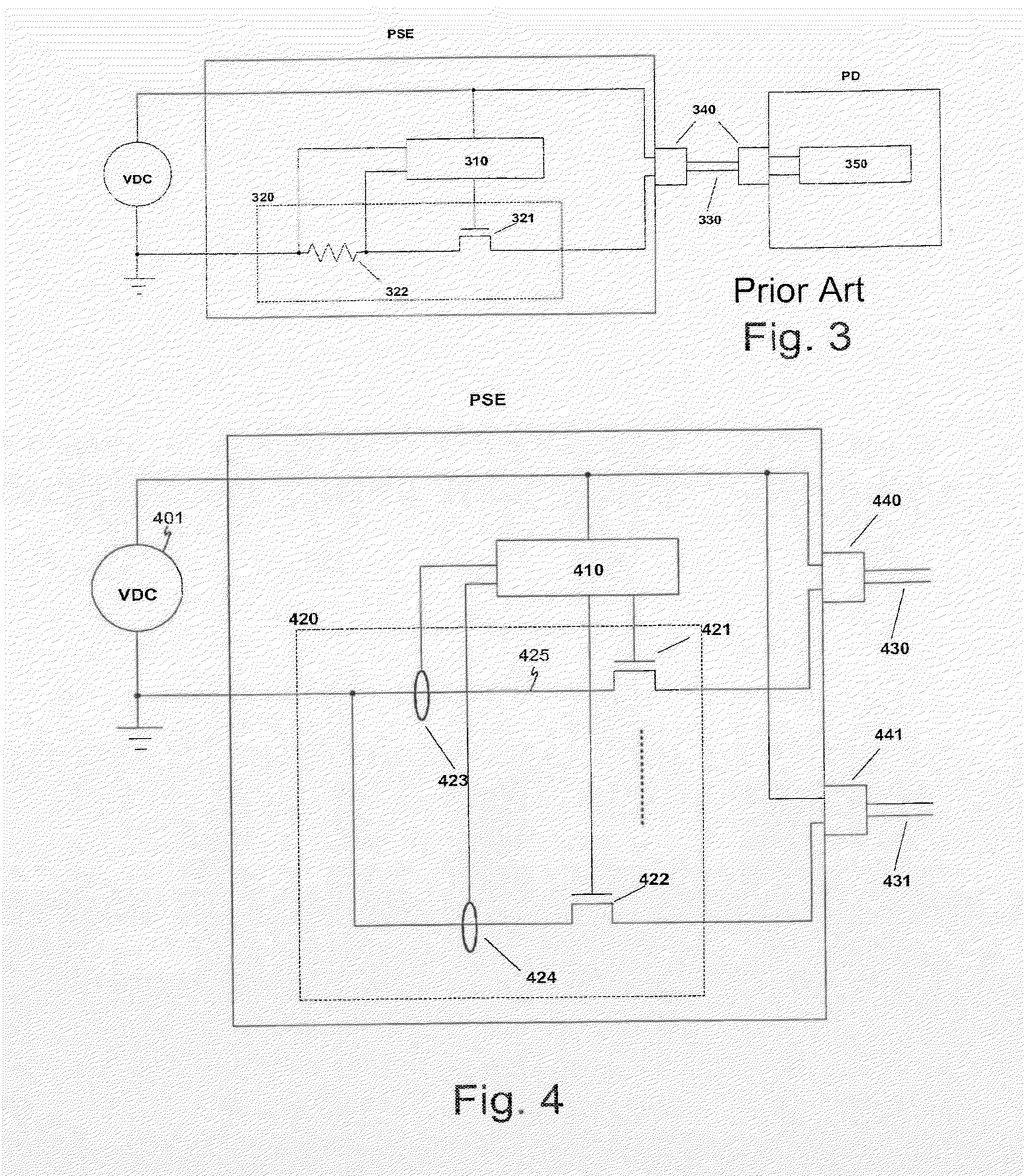
Surprisingly, in spite of the substantial amount of information related to current measurement, no Power over Ethernet equipment provides an alternative to the sense resistor as a mean to measure the current flowing through the power switch of PSE and PD devices.
A further problem of existing Power over Ethernet equipment is a risk of overheating.

Method used


Image

  • Current-Monitoring Apparatus
  • Current-Monitoring Apparatus
  • Current-Monitoring Apparatus

Examples


further embodiment

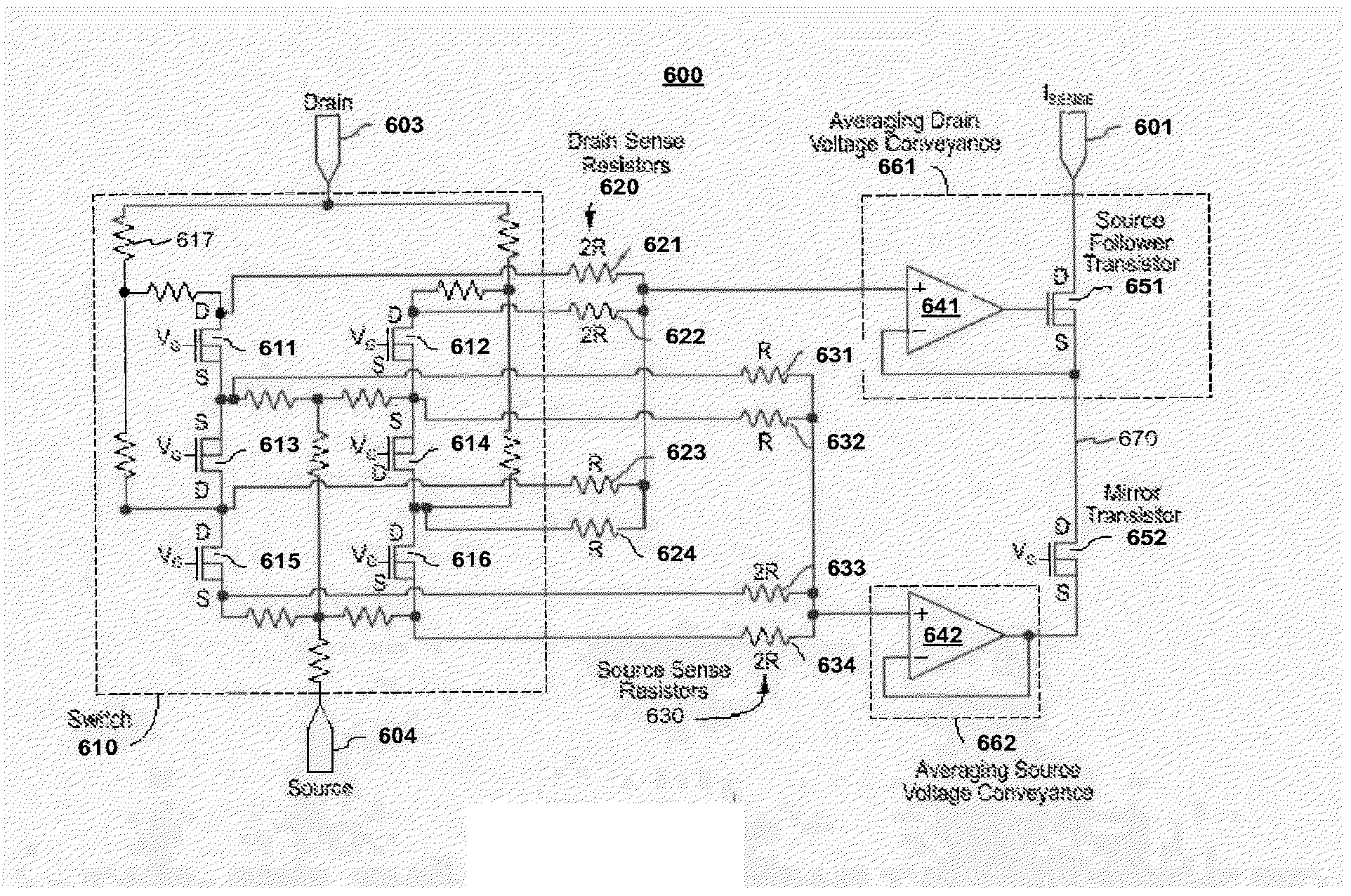
[0130]FIG. 19 shows another embodiment of a switch and current monitoring apparatus. In some applications, the precision of the measurement need not be as high as that obtained with the circuit structures shown above in other embodiments. In such cases, it may be practical to use a measurement structure with fewer components and that dissipates even less power than the structures discussed previously. This is an advantage particularly if the switch and the mirror structure are integrated in the same semiconductor substrate. Such a simplified structure can for example be used for the PD interface.

[0131]As shown in FIG. 19, a cascode current mirror comprising the transistors (5) and (6) is used to copy the drain voltage of the switch transistor (7) and force that voltage on the drain of the sense transistor (8). To guarantee that the bias current flowing in transistors (5) and (6) will be equal (a condition for the cascode structure to operate as desired), transistor (9) is placed in ...


PUM


Abstract

A local area networking apparatus comprises a power stage for connecting to a network cable for carrying power and data. The power stage comprises a main current flow path which includes a switch comprising at least one transistor positioned in the main current flow path and a current monitoring apparatus for monitoring current flow in the main current flow path, and wherein the current monitoring apparatus comprises a sensor which is not placed in series with the main current flow path. The current monitoring apparatus can comprise a current mirroring stage which is arranged to mirror current flowing in the main current flow path to a monitoring current flow path. The switch can be implemented as a set of switches.

Description

CROSS REFERENCE TO RELATED APPLICATIONS[0001]This application is a divisional of U.S. patent application Ser. No. 11 / 676,252, filed on Feb. 16, 2007, which is incorporated herein by reference in its entirety. U.S. patent application Ser. No. 11 / 676,252 claims priority under 35 U.S.C. 119 to European Patent Application serial number 06447102.2 filed Aug. 31, 2006, which European patent application is incorporated herein by reference in its entirety. U.S. patent application Ser. No. 11 / 676,252 is also a continuation-in-part of U.S. patent application Ser. No. 11 / 356,557, filed Feb. 17, 2006, now U.S. Pat. No. 7,525,333, which is also incorporated herein by reference in its entirety.BACKGROUND1. Field[0002]There are various occasions where it is necessary to monitor an amount of current that flows along a path. One example is where current is supplied to a load via a switch. By measuring the current, the current may be regulated to an appropriate value, such as a static current value o...

Claims


Application Information

Patent Timeline
Patent Type & Authority Applications(United States)
IPC IPC(8): G01R19/00G01R35/00
CPCG01R35/005G01R19/0092
Inventor BERTIN, JACQUES J.VAN ROEYEN, STEVANHOUT-MARCHAND, ALEXISGEIRNAERT, KOENJANSSENS, JOHANGOUWY, CHRISTOPHESEVENHANS, JOANNES MATHILDA JOSEPHUS
Owner AVAGO TECH INT SALES PTE LTD
Why Eureka
Try Eureka