

Common mode filter
a filter and mode filter technology, applied in the direction of transformer/inductance details, magnetic bodies, inductances, etc., can solve the problem of difficult to obtain as high noise removal performance as that of the toroidal core, and achieve the effect of reducing the capacitance between different turns, reducing the mode conversion characteristics, and high inductan
- Summary
- Abstract
- Description
- Claims
- Application Information
AI Technical Summary
Benefits of technology
Problems solved by technology
Method used
Image

Examples
first embodiment
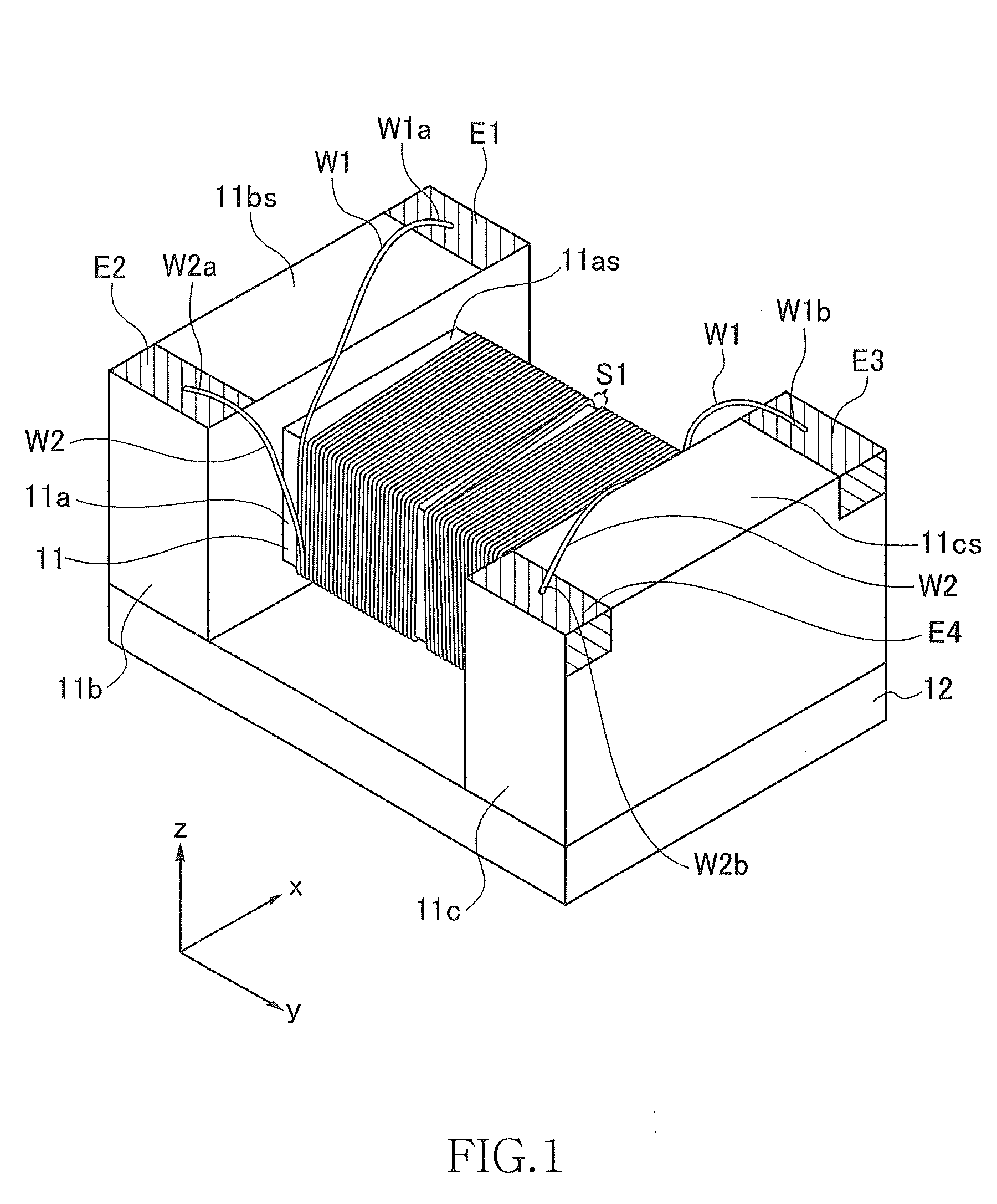
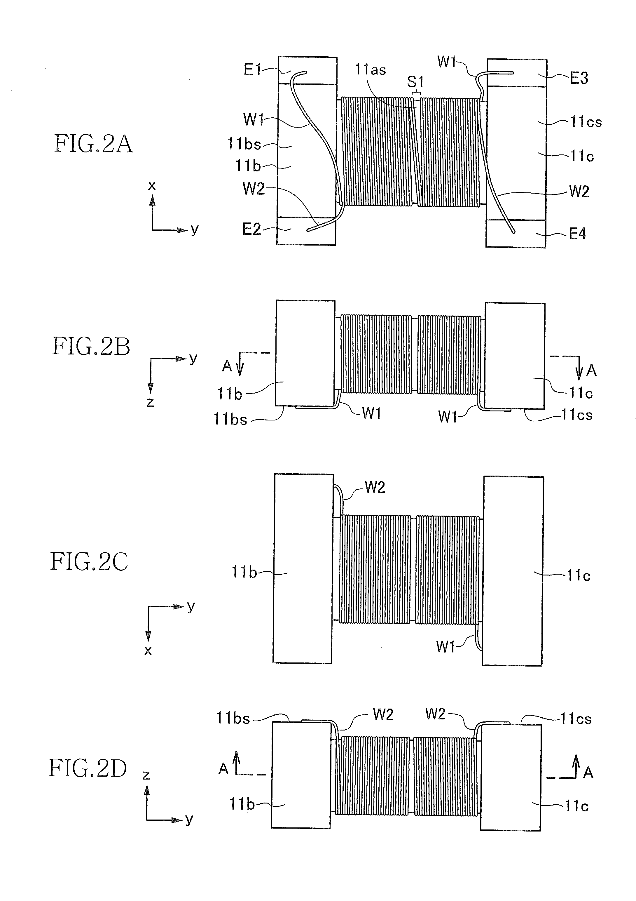
[0037]FIG. 1 is a schematic perspective view of an exterior structure of a surface-mount common mode filter 10 according to the present invention. FIGS. 2A to 2D are plan views of the common mode filter 10 with a plate core 12 (described later) removed, when viewed respectively from four directions in an x-z plane (a plane perpendicular to the y direction). In the present embodiments, as shown in FIG. 1, a direction in which a pair of flange portions 11b and 11c (described later) are opposed to each other is referred to as “y direction”, a direction perpendicular to the y direction in a plane of upper surfaces 11bs and 11cs (described later) is referred to as “x direction”, and a direction perpendicular to both the x direction and the y direction is referred to as “z direction”.
[0038]As shown in FIG. 1, the common mode filter 10 is configured by including a drum core 11, the plate core 12 attached to the drum core 11, and wires W1 and W2 (first and second wires) wound around the dru...
second embodiment
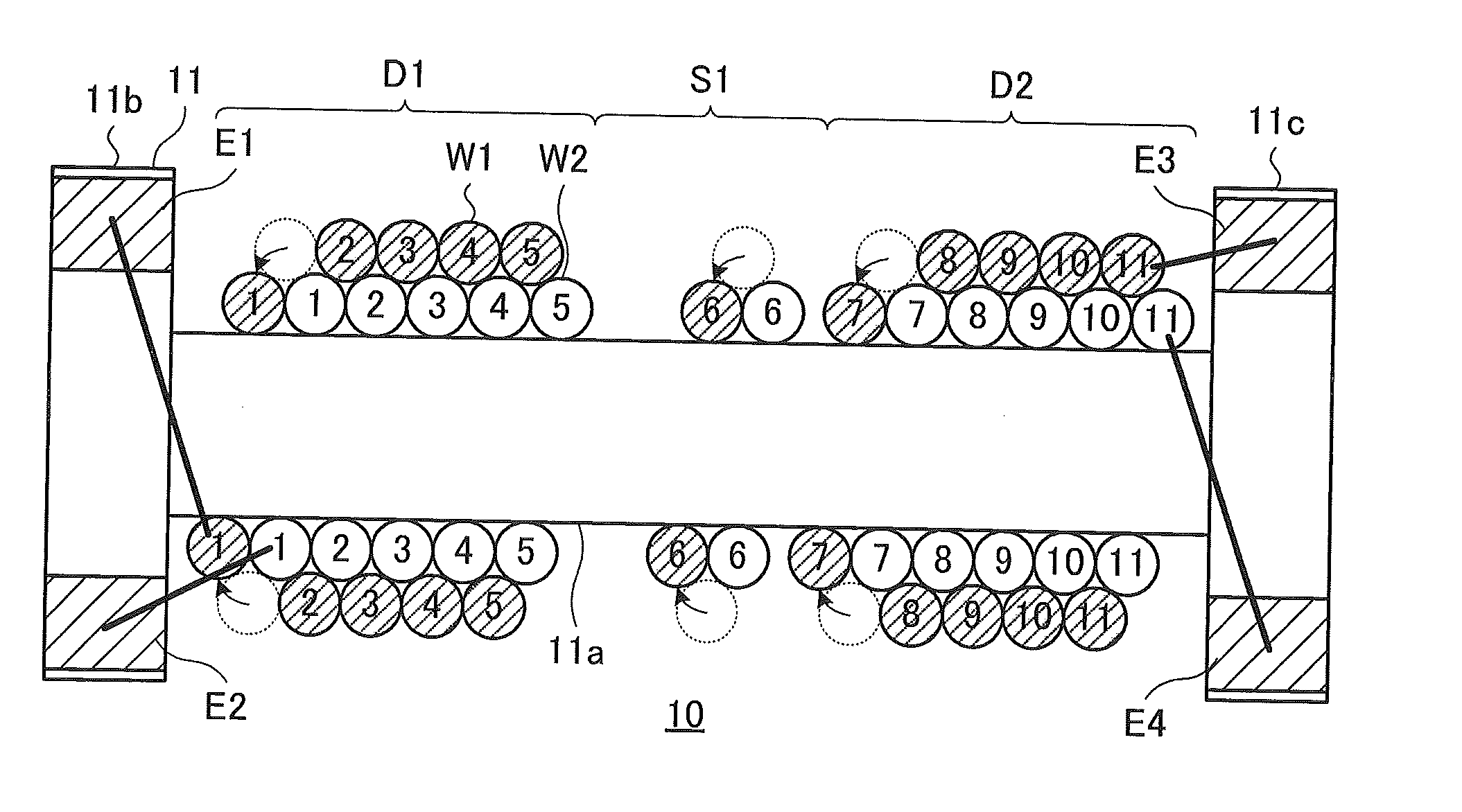
[0058]As shown in FIG. 7, the wires W1 and W2 include first and second sparsely-wound portions 51 and S2 in which the wires W1 and W2 are wound with adjacent pair-wires spaced from each other, and first to third closely-wound portions D1 to D3 in which the wires W1 and W2 are wound with adjacent pair-wires in close contact with each other. The second closely-wound portion D2, the first sparsely-wound portion 51, the first closely-wound portion D1, the second sparsely-wound portion S2, and the third closely-wound portion D3 are arranged in this order from the flange portion 11b to the flange portion 11c. The wires W1 and W2 with the turn numbers 1 to 3 are included in the second closely-wound portion D2. The wires W1 and W2 with the turn number 4 are included in the first sparsely-wound portion S1. The wires W1 and W2 with the turn numbers 5 to 7 are included in the first closely-wound portion D1. The wires W1 and W2 with the turn number 8 are included in the second sparsely-wound p...
third embodiment
[0069]As explained above, the common mode filter 10 can also achieve both reducing the mode conversion characteristics and ensuring a high impedance. Further, because the mounting directionality of the common mode filter 10 can be reduced, it is possible to reduce the operation burden of installing the common mode filter 10 on a substrate, and to prevent mistakes with the installation.
[0070]FIG. 11 is a schematic diagram showing a modification of the winding state of the wires W1 and W2 shown in FIG. 9. In FIG. 11, similarly to FIG. 10, each of a straight line and a broken line connects between cross sections of a wire. The straight line schematically shows the wire located on the front side of the winding core portion 11a in the drawing. The broken line schematically shows the wire located on the rear side of the winding core portion 11a in the drawing. In the present modification, the wires W1 and W2 cross each other (their positions are interchanged) within the first sparsely-wo...
PUM
 Abstract
Description
Claims
Application Information