
Ophthalmic optical coherence tomography system and method for quick switching to realize anterior and posterior eye segments imaging

Active Publication Date: 2014-04-10
SHENZHEN CERTAINN TECH CO LTD
View PDF5 Cites 27 Cited by
  • Summary
  • Abstract
  • Description
  • Claims
  • Application Information

AI Technical Summary

Benefits of technology

The present invention provides an ophthalmic optical coherence tomography system and method for measuring the length of an eye axis. The system allows for quick switching between different depths and real-time imaging, which improves the detection scope of the system and allows for high quality imaging of different eye segments with a relatively high resolution. The switch system works stably and accurately without influencing the signal-to-noise ratio of the system, and can measure objects at different depths.

Problems solved by technology

Eye axial length is a primary issue for judging eye ametropia.
Moreover, resolution of A-scan ultrasonic measurement is relatively low and thus is incapable of measurement with a sufficient accuracy.
Thus, it is incapable of quickly switching between the anterior and posterior eye segments and realizing real-time imaging.
Furthermore, since the measured object will shake its eyes, the measurement of eye axial length is inaccurate with a large error.
Secondly, the imaging quality is bad due to the fact that the cornea and fundus have different shapes and it is unable for a single probe to focus at both of the two locations.

Method used


Image

  • Ophthalmic optical coherence tomography system and method for quick switching to realize anterior and posterior eye segments imaging
  • Ophthalmic optical coherence tomography system and method for quick switching to realize anterior and posterior eye segments imaging
  • Ophthalmic optical coherence tomography system and method for quick switching to realize anterior and posterior eye segments imaging

Examples


Embodiment Construction

[0047]Technical solutions in embodiments of the present invention will be illustrated clearly and entirely with the aid of the drawings in the embodiments of the invention. It is apparent that the illustrated embodiments are only some embodiments of the invention instead of all of them. Other embodiments that a person having ordinary skills in the art obtains based on the illustrated embodiments of the invention without paying any creative work should all be within the protection scope sought by the present invention.

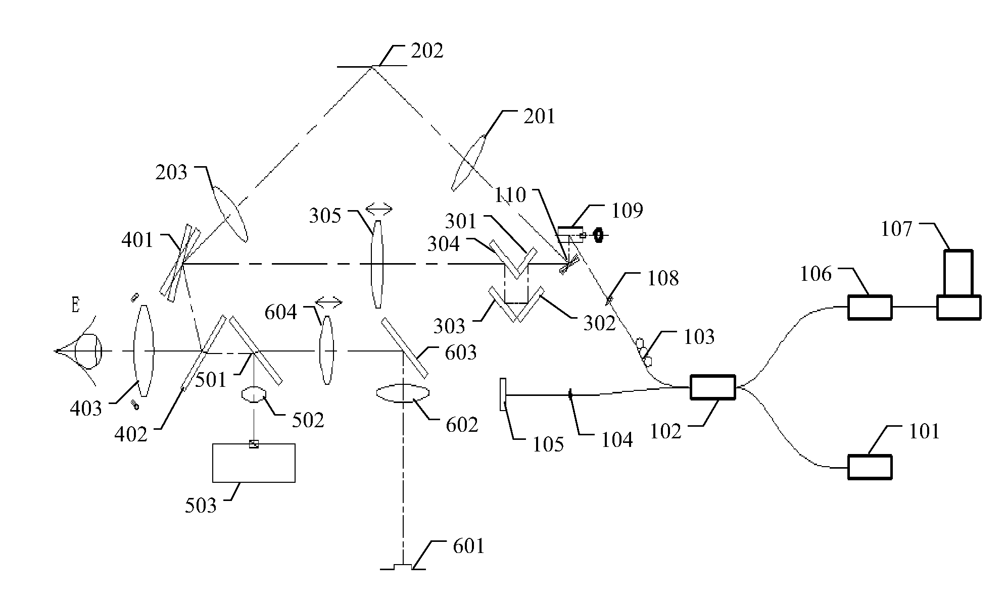
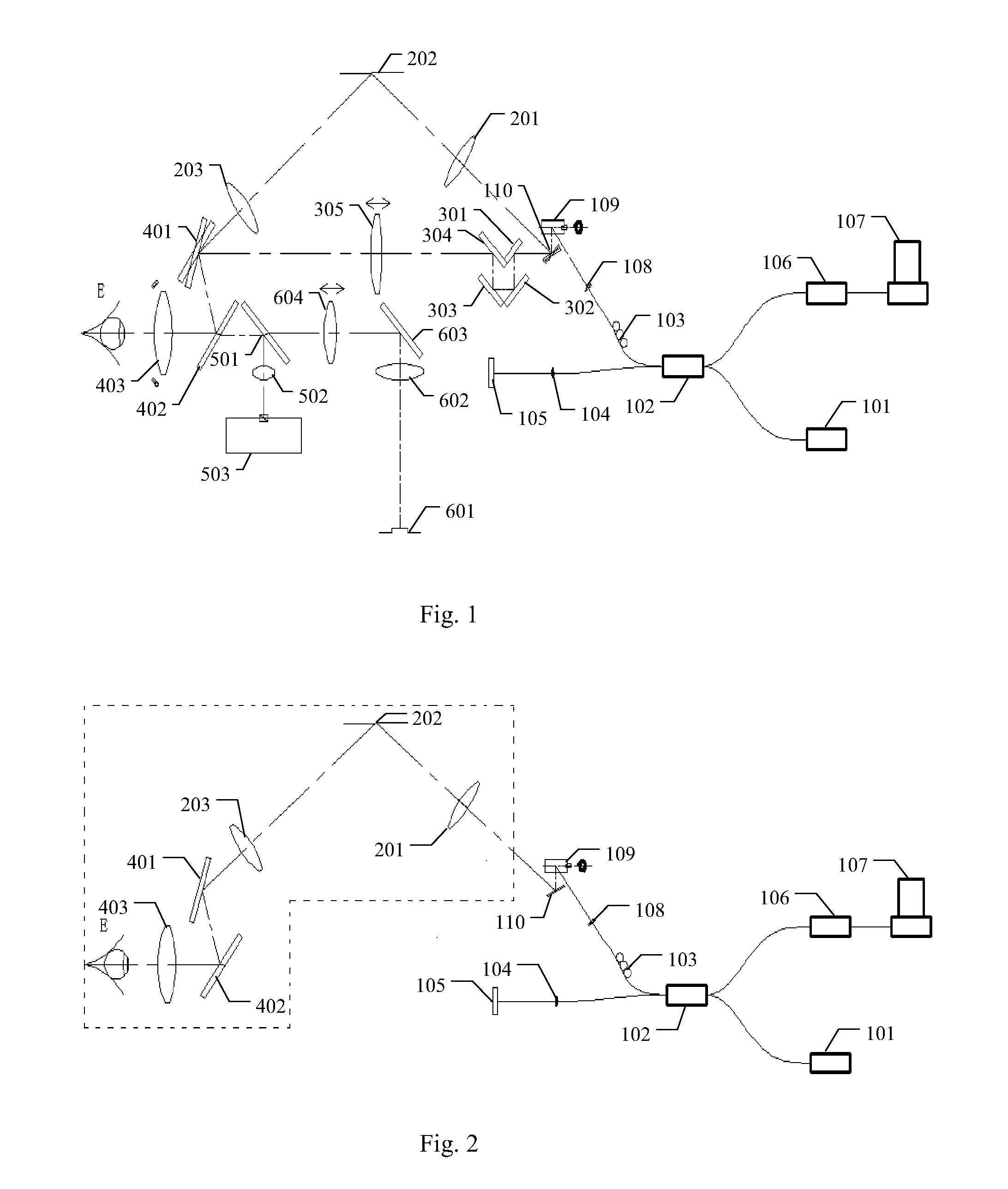
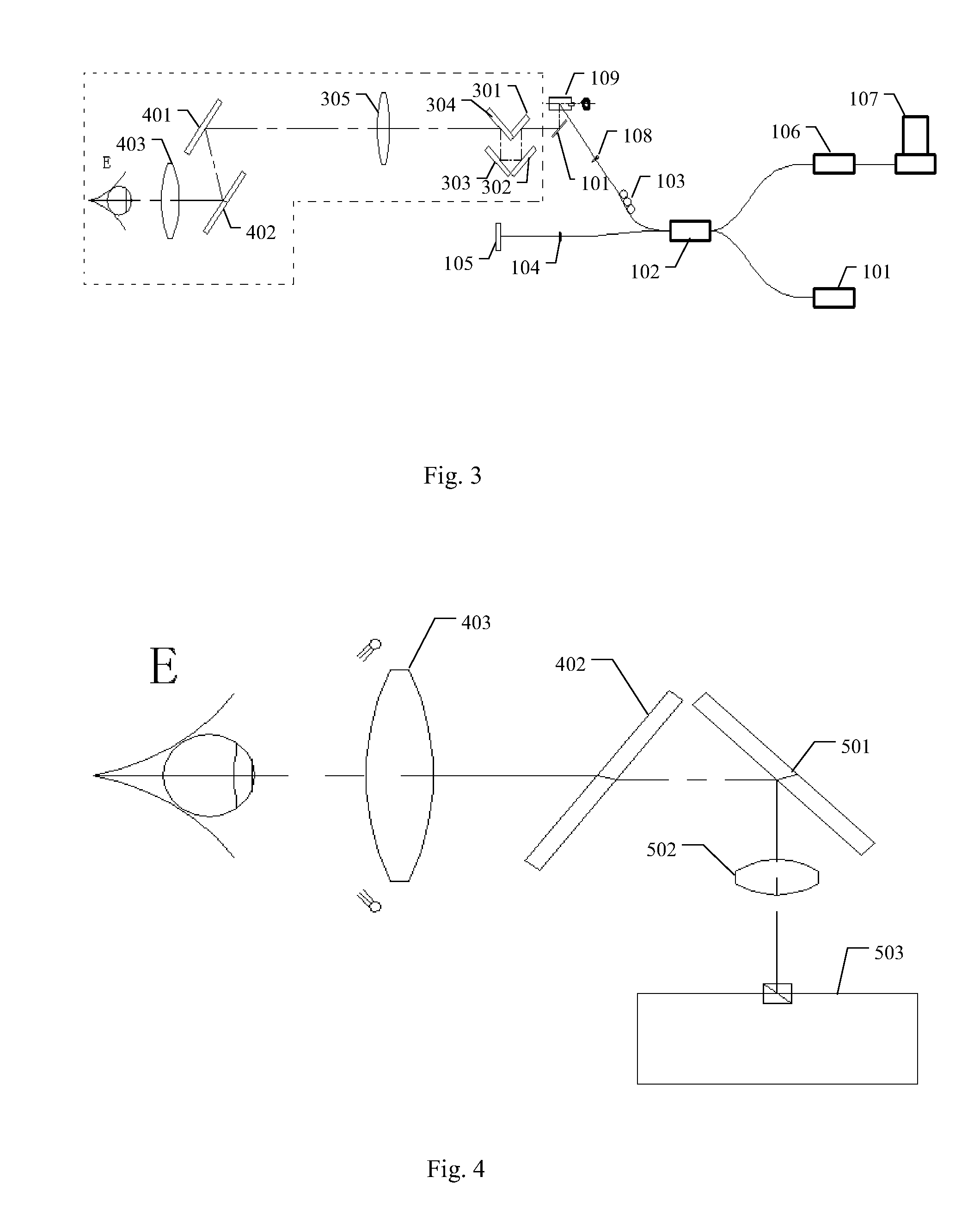
[0048]FIG. 1 is a first schematic structural diagram of an ophthalmic optical coherence tomography system according to an embodiment of the invention. As shown in FIG. 1, the ophthalmic optical coherence tomography system comprises: an ophthalmic optical coherence tomography (OCT) interferometer primary module and a sample arm module. The OCT interferometer primary module includes an OCT light source 101, a fiber coupler 102, a reference arm 104, a detection module 106,...


PUM


Abstract

It is provided an ophthalmic optical coherence tomography system in the invention, the system comprising: an OCT interferometer primary module and a sample arm module, wherein the OCT interferometer primary module comprises an OCT light source, a fiber coupler, a reference arm, a detection module, an X-direction scanning unit, and a Y-direction scanning unit; the sample arm module comprises an anterior eye segment imaging module and a posterior eye segment imaging module; the Y-direction scanning unit is rotatable; when the Y-direction scanning unit is at a first rotation angle, the Y-direction scanning unit reflects the light received by the X-direction scanning unit into the anterior eye segment imaging module; and when the Y-direction scanning unit is at a second rotation angle, the Y-direction scanning unit reflects the light received by the X-direction scanning unit into the posterior eye segment imaging module. It is further provided a method for quick switching to realize anterior and posterior eye segments imaging in the invention, in which imaging at one time and quick switching for locations at different depths can be realized, and on this basis, the eye axial length can be measured accurately.

Description

CROSS REFERENCE TO RELATED APPLICATIONS[0001]The present application is a national stage application of International Application No. PCT / CN2012 / 074577, filed on Apr. 24, 2012, which is hereby incorporated by reference in its entirety.FIELD OF THE INVENTION[0002]The invention relates to opto-electronics technical field, and in particular, to an ophthalmic optical coherence tomography system and a method for quick switching to realize anterior and posterior eye segments imaging.BACKGROUND OF THE INVENTION[0003]Eye axial length is a primary issue for judging eye ametropia. It is also an important indication for discriminating true myopia and pseudomyopia, and for computing parameters of an artificial crystal for a cataract operation.[0004]In existing art, methods for measuring an eye axial length include A-scan ultrasonic measurement and optical measurement. Existing A-scan ultrasonic measurement takes advantage of ultrasonic ranging principle. However, it is necessary to directly tou...

Claims


Application Information

Patent Timeline
IPC IPC(8): A61B3/10
CPCA61B3/102G01B9/02091
Inventor CAI, SHOUDONGLI, PENGGUO, SHUGUANGDAI, XIANGSONGWU, LEI
Owner SHENZHEN CERTAINN TECH CO LTD
Learn More