Method for purging condensate from a charge air cooler

a technology of air cooler and condensate, which is applied in the direction of machine/engine, charge feed system, combustion engine, etc., can solve the problems of increasing the likelihood of engine misfire, engine misfire, condensate may still build up over time, etc., and achieves the effect of increasing air temperature, increasing density, and increasing power

Active Publication Date: 2014-04-17
FORD GLOBAL TECH LLC
View PDF3 Cites 17 Cited by
  • Summary
  • Abstract
  • Description
  • Claims
  • Application Information

AI Technical Summary

Benefits of technology

[0002]Turbocharged and supercharged engines may be configured to compress ambient air entering the engine in order to increase power. Compression of the air may cause an increase in air temperature, thus, a charge air cooler may be utilized to cool the heated air, thereby increasing its density and further increasing the potential power of the engine. Ambient air from outside the vehicle travels across the charge air cooler to cool intake air passing through the inside of the charge air cooler. Condensate may form in the charge air cooler when the ambient air temperature decreases, or during humid or rainy weather conditions, where the intake air is cooled below the water dew point. Condensate may collect at the bottom of the charge air cooler, or in the internal passages, and cooling turbulators. When torque is increased, such as during acceleration, increased mass air flow may strip the condensate from the charge air cooler, drawing it into the engine and increasing the likelihood of engine misfire.

Problems solved by technology

When torque is increased, such as during acceleration, increased mass air flow may strip the condensate from the charge air cooler, drawing it into the engine and increasing the likelihood of engine misfire.
However, the inventors herein have recognized potential issues with such methods.
Specifically, while some methods may reduce or slow condensate formation in the charge air cooler, condensate may still build up over time.
If this build-up cannot be stopped, ingestion of the condensate during acceleration may cause engine misfire.
While this may reduce condensate levels in the charge air cooler, condensate is moved to an alternate location or reservoir, which may be subject to other condensate problems such as freezing and corrosion.
The increase in air flow through the charge air cooler and resultant torque disturbance that may occur if the air flow were to reach the engine, may be counteracted by routing a portion of the air from the charge air cooler back to the intake passage upstream of the compressor.
In this way, the clean-out cycle may not alert the vehicle operator.

Method used


Image

  • Method for purging condensate from a charge air cooler
  • Method for purging condensate from a charge air cooler
  • Method for purging condensate from a charge air cooler

Examples


Embodiment Construction

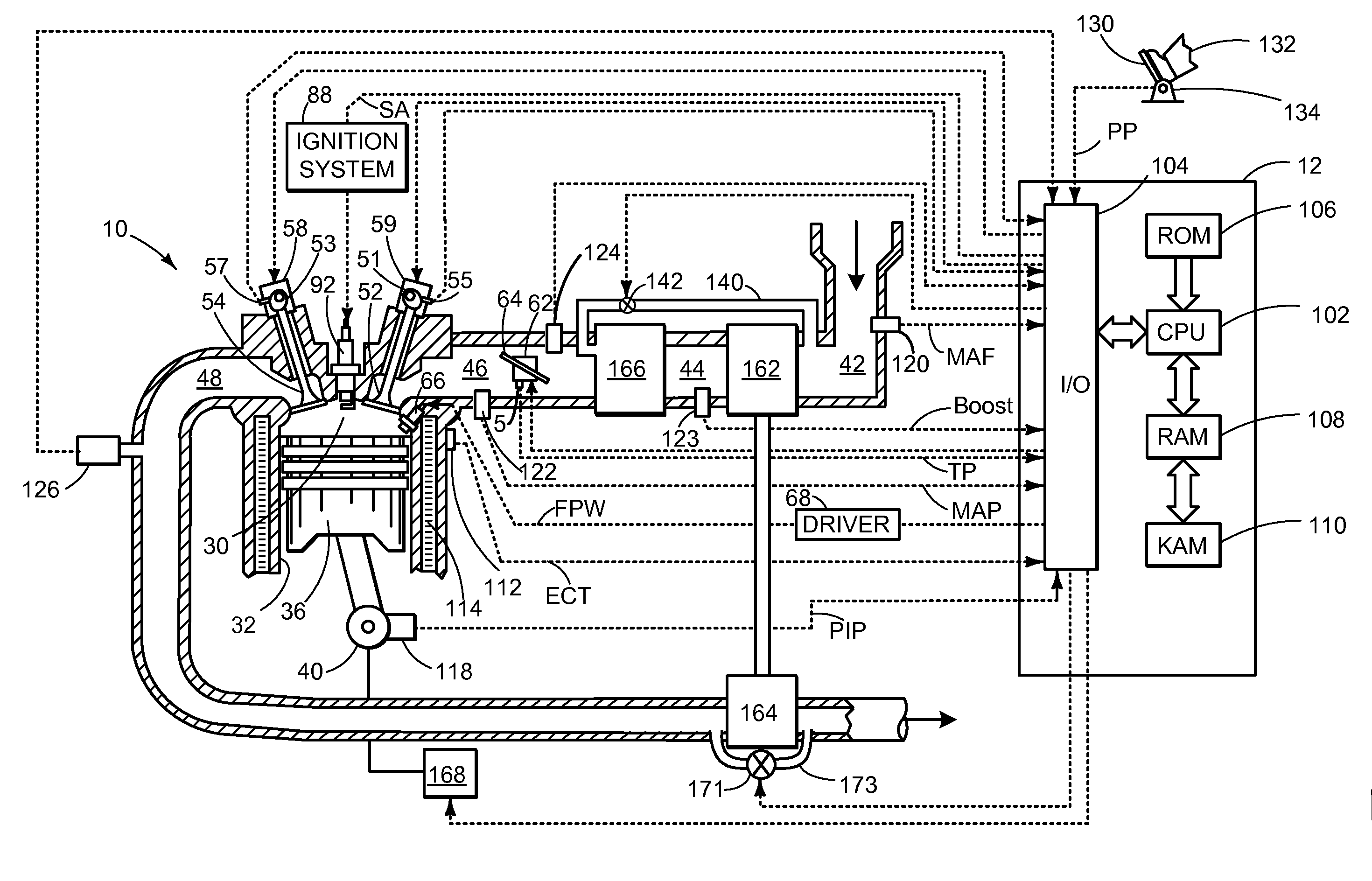
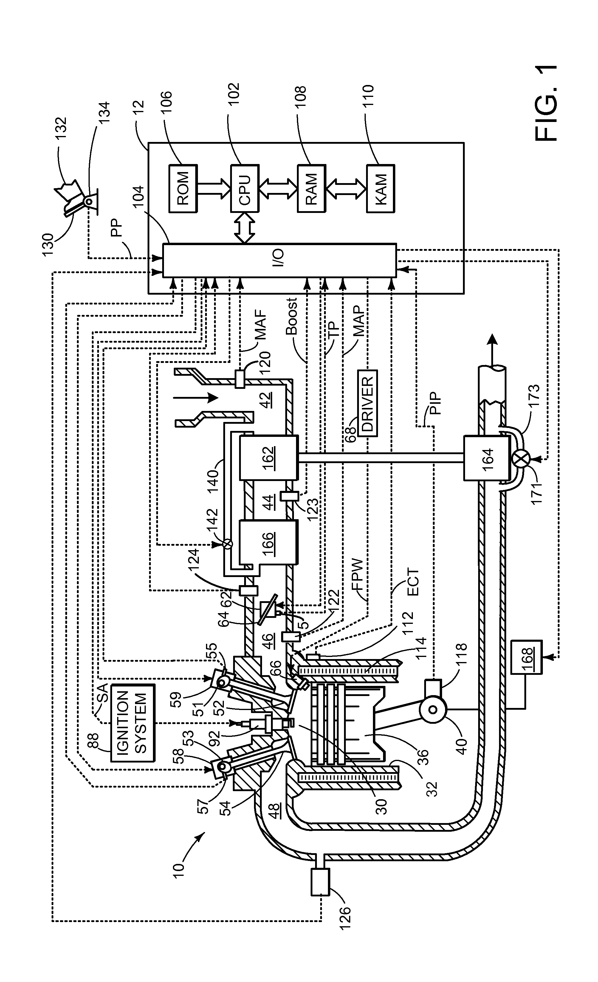
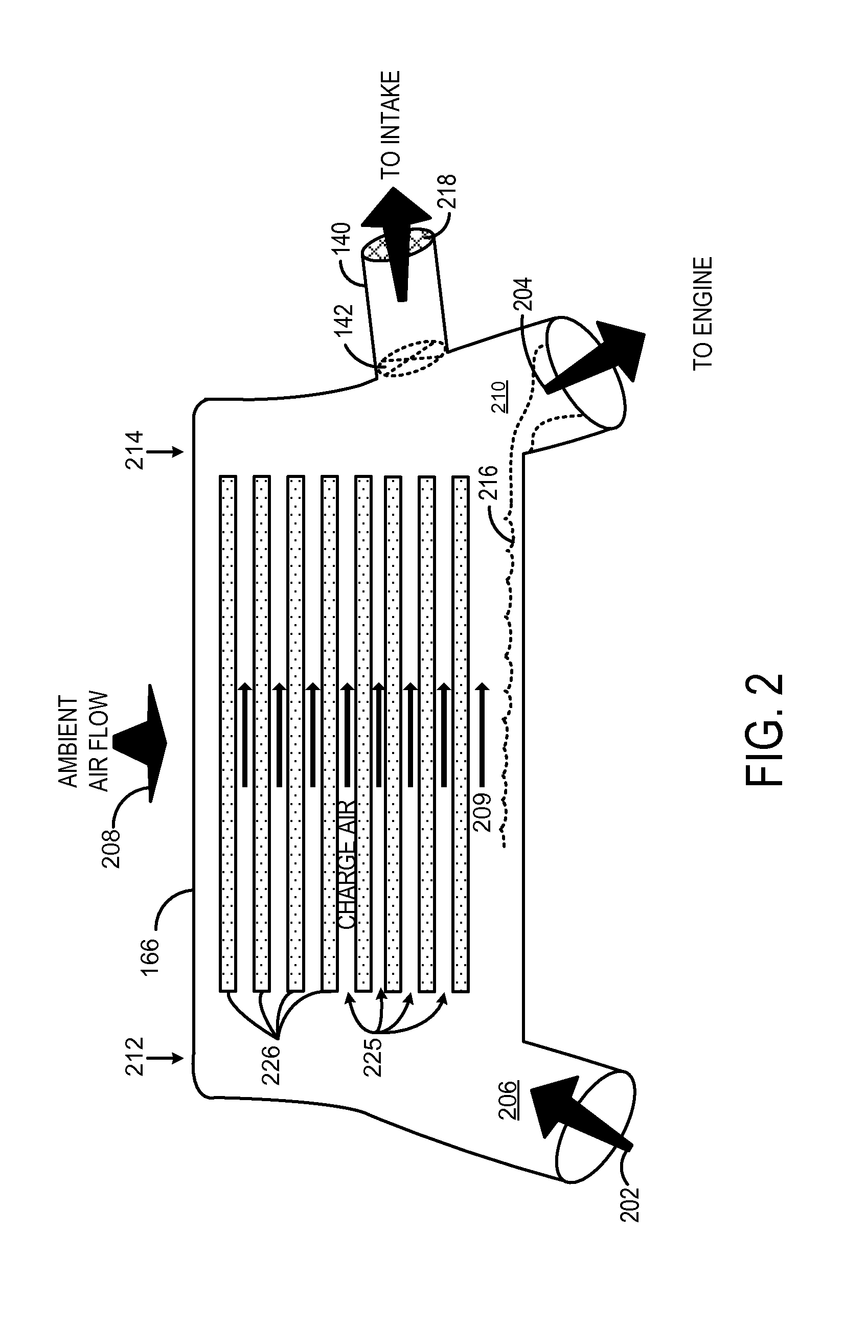
[0012]During a standard engine drive cycle, engine air flow may be periodically raised for short durations, termed micro tip-ins, due to vehicle traversal of small hills, ambient air flow changes, vehicle acceleration, etc. These micro tip-ins may act to gradually remove condensate that has built up in an engine charge air cooler. However, under certain conditions, such as when the vehicle is driven over a flat surface, the micro tip-ins may not occur frequently enough to adequately remove the accumulated condensate. Thus, if engine air flow remains below a threshold for a given amount of time, a charge air cooler clean-out cycle may be initiated to actively remove the accumulated condensate.

[0013]The clean-out cycle may be performed by closing a turbocharger wastegate, thus increasing boost pressure and air flow through the charge air cooler. This increased air flow may gradually remove the condensate from the charge air cooler and direct the condensate to the engine in a controlle...


PUM


Abstract

Embodiments for controlling condensate in a charge air cooler are provided. In one example, a method for a charge air cooler comprises, responsive to a condensate level in the charge air cooler, increasing boost pressure and maintaining a requested level of torque by routing a portion of air flow exiting the charge air cooler to an intake passage upstream of a compressor. In this way, accumulated condensate in the charge air cooler may be removed while maintaining driver-requested torque.

Description

FIELD[0001]The present disclosure relates to a charge air cooler.BACKGROUND AND SUMMARY[0002]Turbocharged and supercharged engines may be configured to compress ambient air entering the engine in order to increase power. Compression of the air may cause an increase in air temperature, thus, a charge air cooler may be utilized to cool the heated air, thereby increasing its density and further increasing the potential power of the engine. Ambient air from outside the vehicle travels across the charge air cooler to cool intake air passing through the inside of the charge air cooler. Condensate may form in the charge air cooler when the ambient air temperature decreases, or during humid or rainy weather conditions, where the intake air is cooled below the water dew point. Condensate may collect at the bottom of the charge air cooler, or in the internal passages, and cooling turbulators. When torque is increased, such as during acceleration, increased mass air flow may strip the condensa...

Claims


Application Information

Patent Timeline
Patent Type & Authority Applications(United States)
IPC IPC(8): F02M15/00
CPCF02B29/0468F02B37/16Y02T10/12F02B29/04
Inventor NORMAN, KRISTOFOR ROBERT
Owner FORD GLOBAL TECH LLC
Why Eureka
Try Eureka