Impact rotation tool
a technology of impact rotation and tool, which is applied in the direction of screwdrivers, power-driven tools, wrenches, etc., can solve the problems of sensor output value having a tendency to contain noise, fastener such as bolts or screws, and may be over-tightened by a large torque,
- Summary
- Abstract
- Description
- Claims
- Application Information
AI Technical Summary
Benefits of technology
Problems solved by technology
Method used
Image
Examples
first embodiment
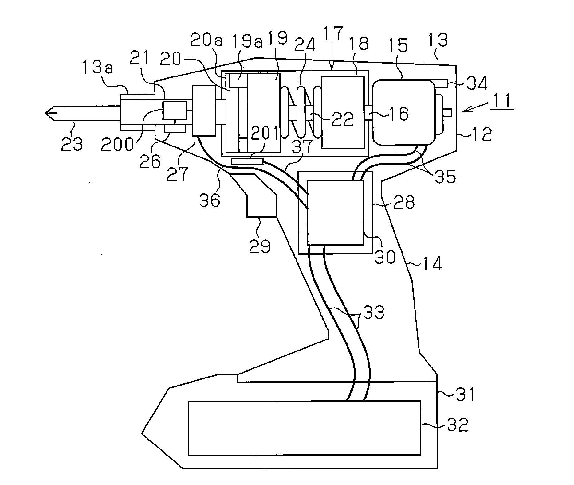
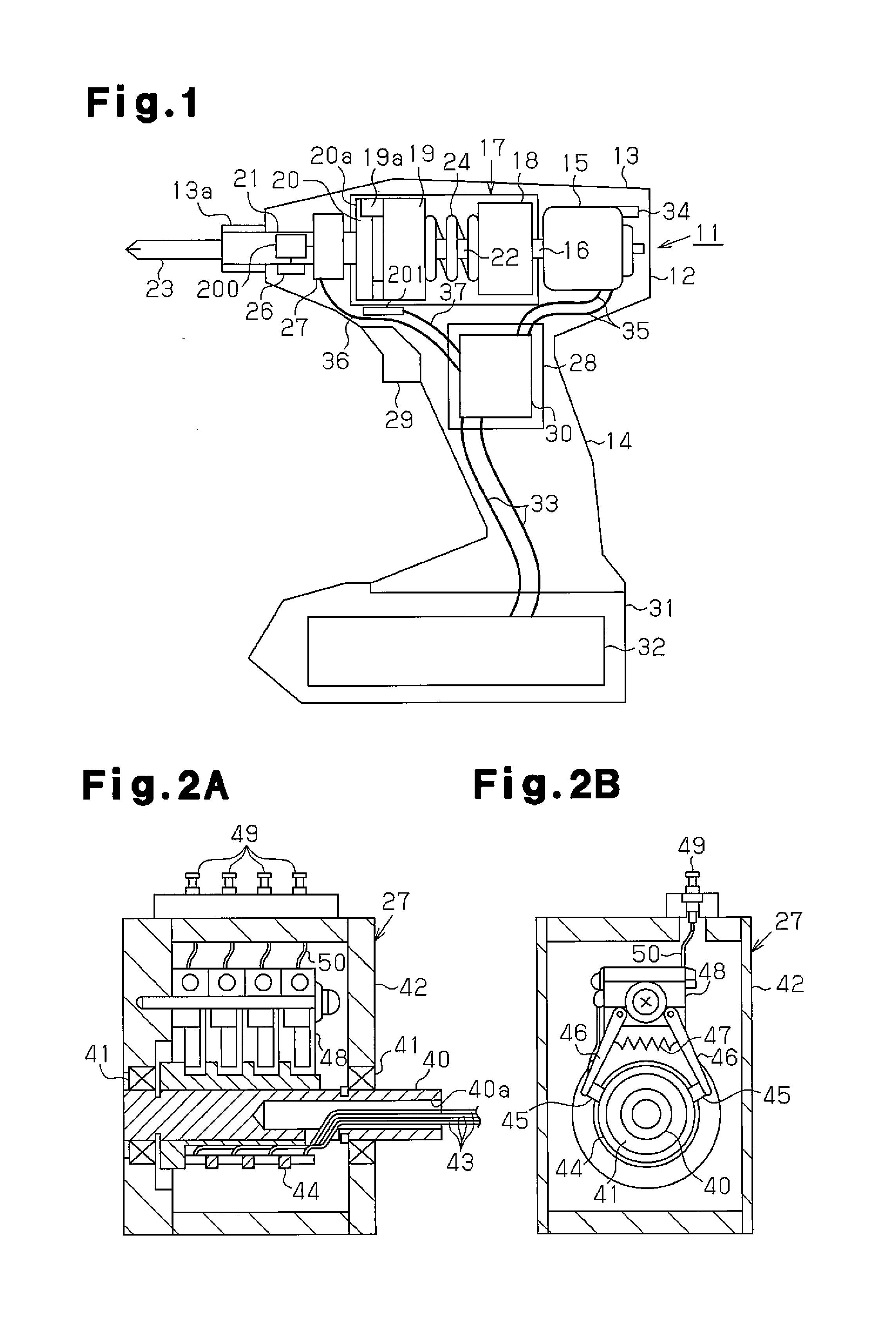
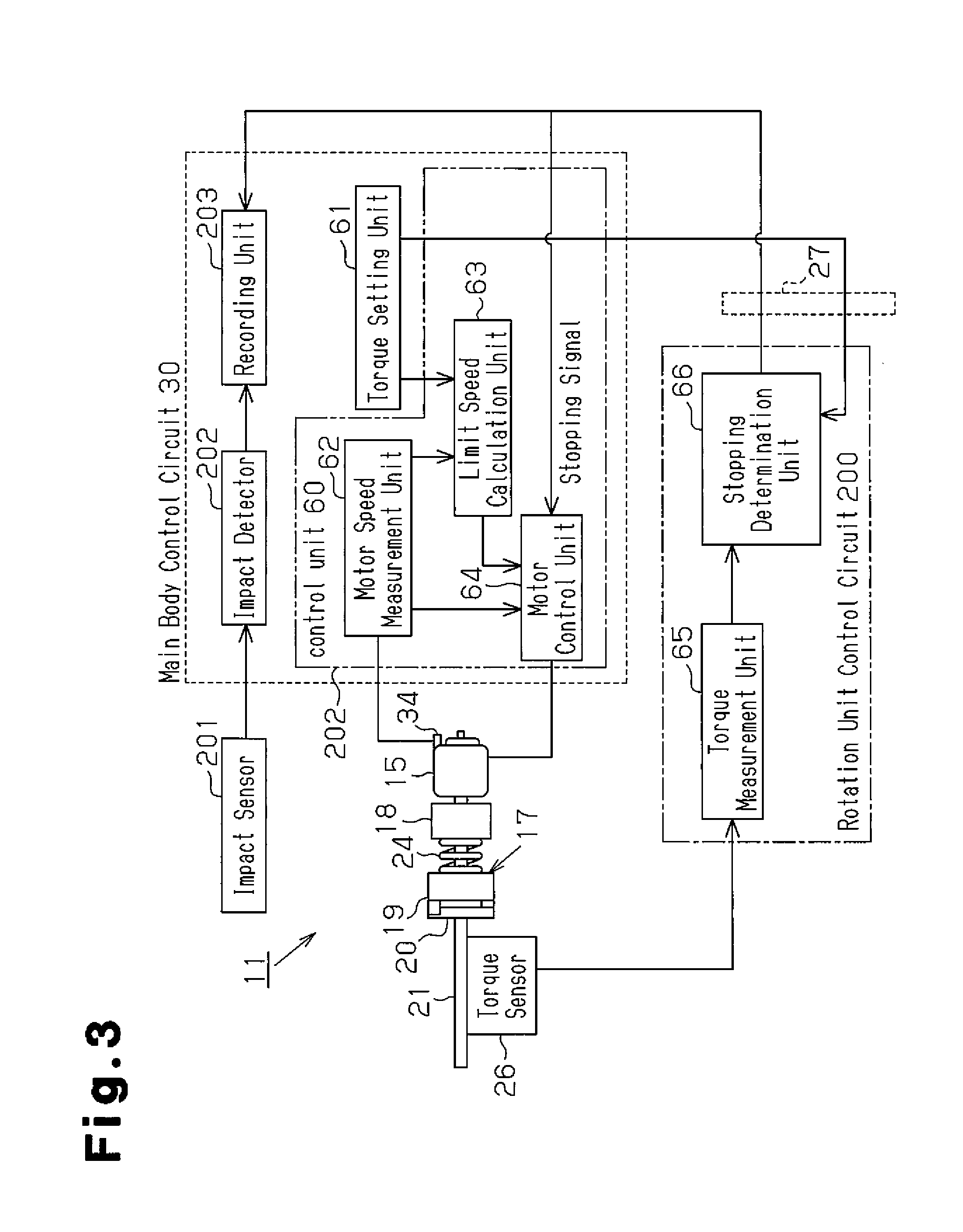
[0031]A first embodiment of an impact rotation tool will now be described with reference to FIGS. 1 to 6.
[0032]FIG. 1 shows an impact rotation tool 11 that is of a hand-held type and held by a single hand. The impact rotation tool 11 may be, for example, an impact driver or an impact wrench. A main body housing 12, which forms the casing of the impact rotation tool 11, includes a barrel 13 and a handle 14, which extends from the barrel 13. The handle 14 extends downward, as viewed in FIG. 1, in a direction intersecting the axis of the barrel 13.
[0033]A motor 15 is arranged in the barrel 13 at a basal side, which is the right side as viewed in FIG. 1. The axis of the motor 15 lies along the axis of the barrel 13. The motor 15 includes an output shaft 16 that faces toward a distal side of the barrel 13. The motor 15 is a DC motor and may be a brushed motor or a brushless motor. An impact force generation unit 17 is coupled to the output shaft 16 of the motor 15. The impact force gener...
second embodiment
[0073]A second embodiment of an impact rotation tool will now be described with reference to FIGS. 7 to 10. The impact rotation tool of the second embodiment differs from that of the first embodiment in how the output shaft 16 is rotated after the stopping signal S is provided from the stopping determination unit 66. The difference will now be described in detail.
[0074]As described above, the motor control unit 64 that receives the stopping signal S from the stopping determination unit 66 stops driving the motor 15. In this case, the hammer 19 may strike the anvil 20 until the output shaft 16 stops rotating. When the hammer 19 strikes the anvil 20 before the output shaft 16 stops rotating, the impact pulse I after the stopping determination unit 66 generates the stopping signal S may differ from the impact pulse I immediately before the stopping determination unit 66 generates the stopping signal S.
[0075]Referring to FIG. 7, when the hammer 19 strikes the anvil 20 before the output ...
third embodiment
[0082]A third embodiment of an impact rotation tool will now be described with reference to FIGS. 11 and 12. The impact rotation tool of the third embodiment differs from that of the first embodiment in that two slip ring units are arranged on the main shaft 21. The difference will now be described in detail.
[0083]Two slip ring units are arranged along the axial direction of the main shaft 21. The first slip ring unit is connected to the stopping determination unit 66 of the rotation unit control circuit 200. The stopping determination unit 66 provides the stopping signal S to the main body control circuit 30 via the first slip ring unit. The second slip ring is connected to the torque measurement unit 65 of the rotation unit control circuit 200. The torque measurement unit 65 provides the torque value to the main body control circuit 30 via the second slip ring unit.
[0084]Referring to FIG. 11, the stopping signal S from the stopping determination unit 66 is provided to the main bod...
PUM
 Abstract
Description
Claims
Application Information
 - R&D
- Intellectual Property
- Life Sciences
- Materials
- Tech Scout
- Unparalleled Data Quality
- Higher Quality Content
- 60% Fewer Hallucinations
Browse by: Latest US Patents, China's latest patents, Technical Efficacy Thesaurus, Application Domain, Technology Topic, Popular Technical Reports.
© 2025 PatSnap. All rights reserved.Legal|Privacy policy|Modern Slavery Act Transparency Statement|Sitemap|About US| Contact US: help@patsnap.com


