
Electric machine having an axial spring element

Active Publication Date: 2014-04-17
ROBERT BOSCH GMBH
View PDF6 Cites 3 Cited by
  • Summary
  • Abstract
  • Description
  • Claims
  • Application Information

AI Technical Summary

Benefits of technology

The axial spring element described in this patent ensures a secure and easy way to mount a spring in an electric machine. It eliminates the need for structural changes to the rotor and reduces design costs. The spring element is connected to the rotor without interfering with its operation. It compensates for any tolerances in the manufacturing process and ensures a direct connection between the rotor and the spring, preventing any relative movement during operation. The method involves fitting the spring element onto the rotor shaft before inserting the rotor into the housing, with the resulting retaining elements securing the spring element against dropping out.

Problems solved by technology

This lead to expenditure incurred for the change and / or to increases in the expenditure for the design of the components relating to the rotor, in particular the rotor body.
As a result of the clamping connection between the retaining elements of the spring element and the rotor, acceleration forces of the rotor can be transmitted directly to the spring element, with the result that a relative movement in the form of a slip between the rotor and the spring element is no longer possible during the operation of the motor.

Method used


Image

  • Electric machine having an axial spring element
  • Electric machine having an axial spring element
  • Electric machine having an axial spring element

Examples


Embodiment Construction

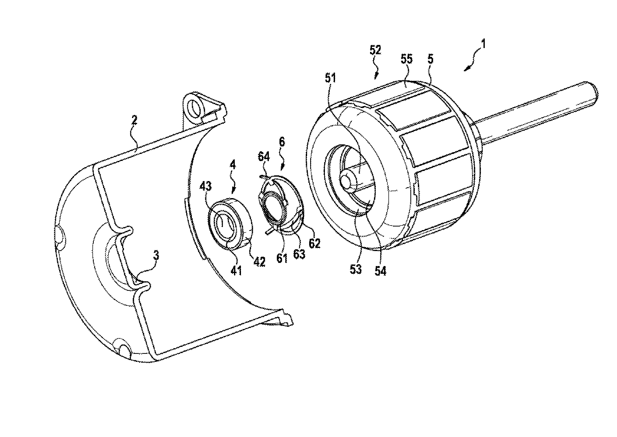
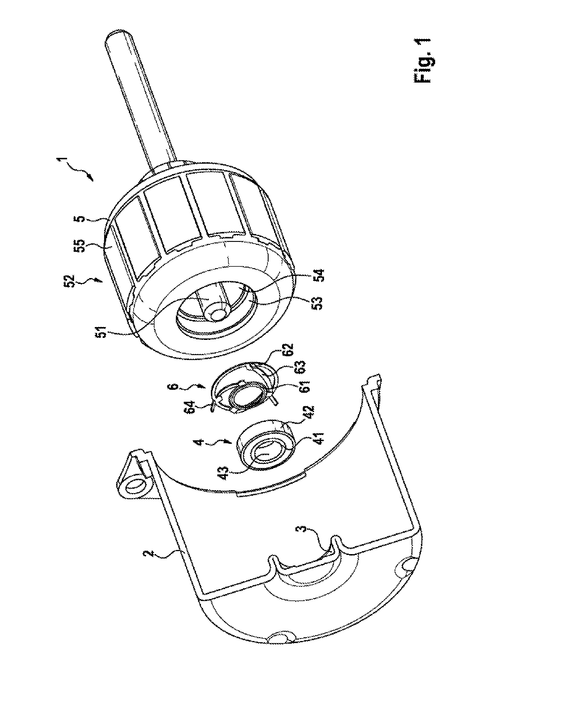
[0025]FIG. 1 illustrates a perspective exploded illustration of a part of an electric machine 1. In the present exemplary embodiment, the electric machine 1 corresponds to an internal rotor electric motor. The electric machine 1 comprises a housing part 2, which is embodied as a pole pot. The pole pot can be embodied in one piece from a metallic material, for example by deep drawing or comparable manufacturing methods.

[0026]The housing part 2 has at its front-side end a circular-cylindrical recess 3 in which a bearing 4 in the form of a ball bearing or roller bearing can be accommodated. In the mounted state, the bearing 4 is accommodated completely or partially in the recess 3 and retained against slipping at least in the radial direction by the peripheral wall of the recess 3. The bearing 4 is embodied in a conventional way with an internal part 41 and an external part 42 which are arranged in a rotational fashion with respect to one another by means of rollers or balls (not shown...


PUM


Abstract

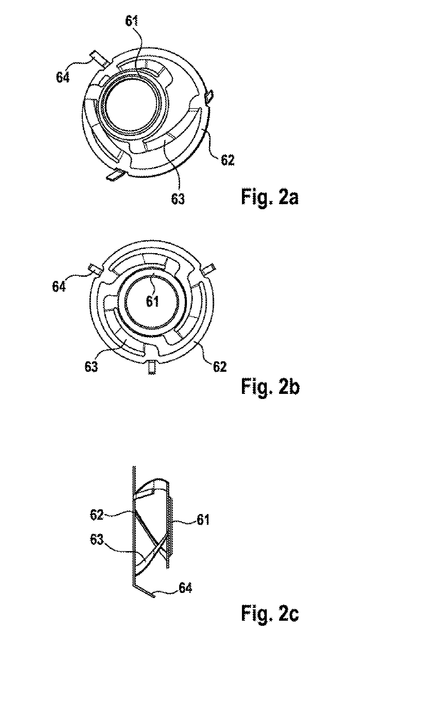
The invention relates to an axial spring element (6) having two peripheral ring elements (61, 62) that are spaced from one another in the axial direction and are connected to one another in a spring-elastic manner, wherein at least one of the ring elements (61) comprises one or more retaining elements (64) in order to brace the spring element with a rotor (5) and thereby hold the spring element on the rotor (5).

Description

BACKGROUND OF THE INVENTION[0001]The invention relates in general to rotary electric machines, in particular electric machines in which an axial spring element is arranged between the rotor body and the bearing of the rotor shaft.[0002]In electric machines having an internal rotor, a rotor body which bears a rotor armature is generally arranged on a rotor shaft. The rotor shaft is mounted in a housing of the electric machine by means of corresponding ball bearings.[0003]Document JP 2000 30 8305 A also discloses that arranged between a ball bearing and the rotor body on the rotor shaft is a washer which supports the rotor axially with respect to the ball bearing. In this context, the washer is embodied as a spring element with a ring part on which radially protruding spring parts are integrally formed, said spring parts being supported in a sprung fashion on the rotor armature. Document DE 2004 041 074 A1 discloses an electric machine in which the axial spring element is fixedly atta...

Claims


Application Information

Patent Timeline
IPC IPC(8): H02K5/16H02K15/00F16F1/26
CPCH02K5/16H02K15/00F16F1/26F16C25/083H02K5/173H02K5/1732F16C2380/26Y10T29/49012
Inventor SUAREZ-SEMINARIO, DARIUSZRICHTER, FRANK
Owner ROBERT BOSCH GMBH
Learn More