Controlled lens antenna apparatus and system

a lens antenna and control technology, applied in the direction of antennas, electrical equipment, etc., can solve the problems of requiring operators to acquire more, requiring only discrete switching of directivity, and requiring a large and more expensive i

Active Publication Date: 2014-04-17
SAMSUNG ELECTRONICS CO LTD
View PDF5 Cites 107 Cited by
  • Summary
  • Abstract
  • Description
  • Claims
  • Application Information

AI Technical Summary

Benefits of technology

[0007]This Summary is provided to introduce a selection of concepts in a simplified form that are further described below in the Detailed Description. This Summary is not intended to identify key features or essential features of the claimed subject matter, nor is it intended to be used as an aid in determining the scope of the claimed subject matter.

Problems solved by technology

But this spectrum is heavily used, making it difficult for operators to acquire more of it.
However, one of the many drawbacks of existing ultra-compact antennas is that they allow executing only discrete switching of directivity.
For smooth scanning in known solutions the increasing of number of antennas on IC is required that leads to increasing of the dimensions of IC, thereby producing a larger and more expensive IC.

Method used


Image

  • Controlled lens antenna apparatus and system
  • Controlled lens antenna apparatus and system
  • Controlled lens antenna apparatus and system

Examples


Embodiment Construction

[0037]The following detailed description is provided to assist the reader in gaining a comprehensive understanding of the methods, apparatuses, and / or systems described herein. Accordingly, various changes, modifications, and equivalents of the systems, apparatuses, and / or methods described herein will be suggested to those of ordinary skill in the art. The progression of processing steps and / or operations described is an example; however, the sequence of steps and / or operations is not limited to that set forth herein and may be changed as is known in the art, with the exception of steps and / or operations necessarily occurring in a certain order. Also, description of well-known functions and constructions may be omitted for increased clarity and conciseness.

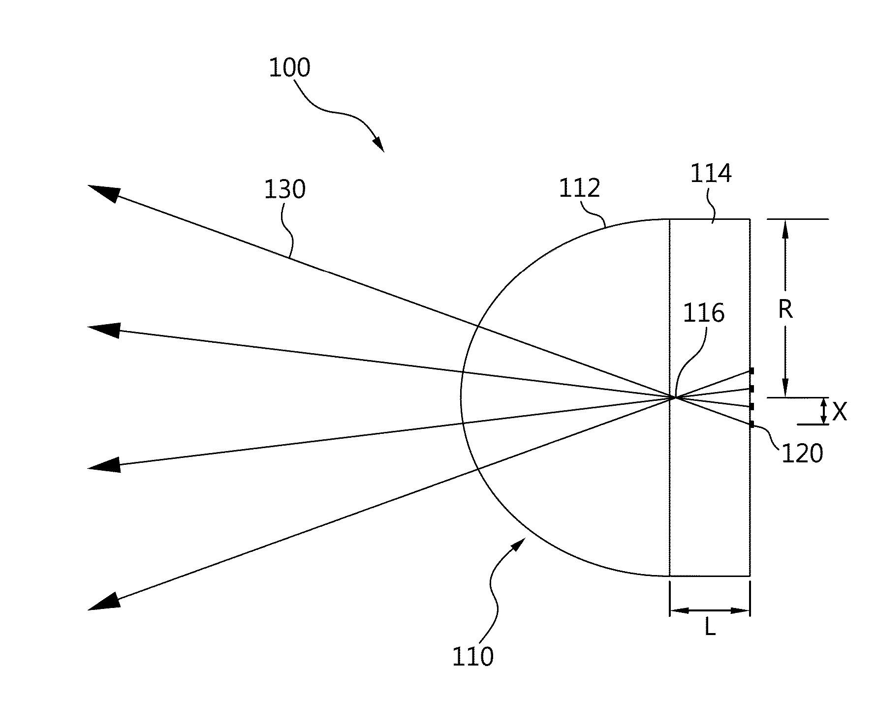
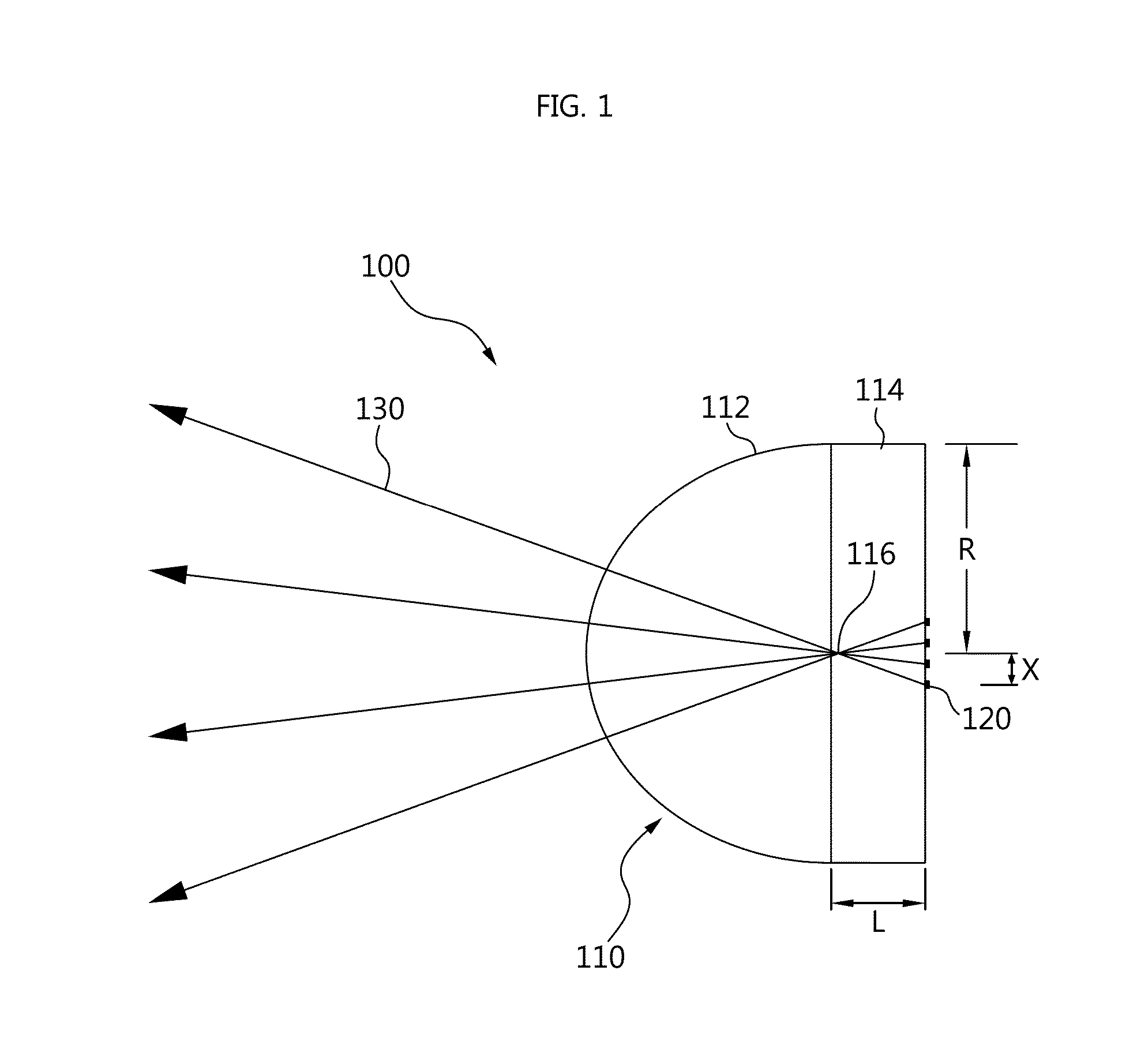
[0038]In accordance with an illustrative configuration, a compact lens antenna apparatus is presented enabling a smooth directivity variation without increasing dimensions and manufacturing costs of an integrated circuit (IC). In...


PUM


Abstract

Present configuration concerns microelectronics; for instance, compact antenna devices applied in mobile communications and other equipment operating in millimeter range. The controlled lens antenna apparatus may include antenna elements in an integrated circuit configured to transmit beams. The apparatus may also include a dielectric lens antenna configured to generate a plane wave based in the beams transmitted. The apparatus may include a plate configured to deflect the generated plane wave at a random angle.

Description

CROSS-REFERENCE TO RELATED APPLICATION(S)[0001]This application claims the benefit under 35 U.S.C. §119(a) of Russian Patent Application No. 2012-144224, filed on Oct. 17, 2012, in the Russian Intellectual Property Office, and Korean Patent Application No. 10-2013-0122753 filed on Oct. 15, 2013, in the Korean Intellectual Property Office, the entire disclosures of which are incorporated herein by reference for all purposes.BACKGROUND[0002]1. Field[0003]The following description relates to a compact and controlled lens antenna to enable continuous directivity variation in a mobile communication equipment operating in a millimeter range.[0004]2. Description of Related Art[0005]In a development and manufacturing of semi-conductor integrated circuits (IC), one of the many focuses in recent years has been to reduce a size of the IC by reducing in size while increasing a number components being integrated in the IC, thereby increasing a package density of the IC and providing a maximum op...

Claims


Application Information

Patent Timeline
Patent Type & Authority Applications(United States)
IPC IPC(8): H01Q15/02
CPCH01Q15/02H01Q3/245H01Q15/08H01Q19/062
Inventor CHERNOKALOV, ALEXANDER GUENNADIEVICHNIKISHOV, ARTEM YURIEVICHDUNAEVA, MARIA ANDREEVNA
Owner SAMSUNG ELECTRONICS CO LTD
Why Eureka
Try Eureka