
Discharge-pumped gas laser device

a laser device and gas pump technology, applied in the direction of laser details, active medium materials, electrical devices, etc., can solve problems such as drop in resolution

Active Publication Date: 2014-04-17
GIGAPHOTON
View PDF9 Cites 6 Cited by
  • Summary
  • Abstract
  • Description
  • Claims
  • Application Information

AI Technical Summary

Benefits of technology

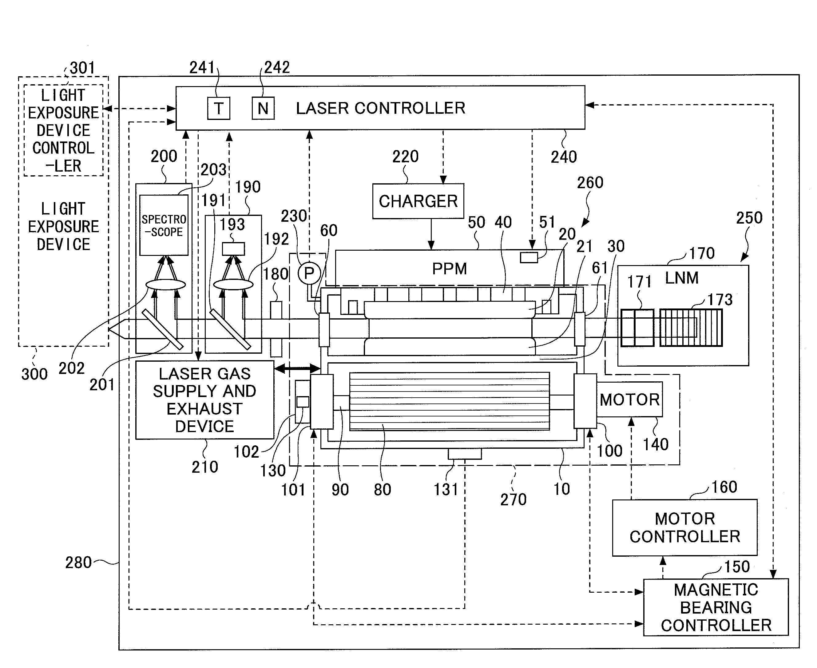
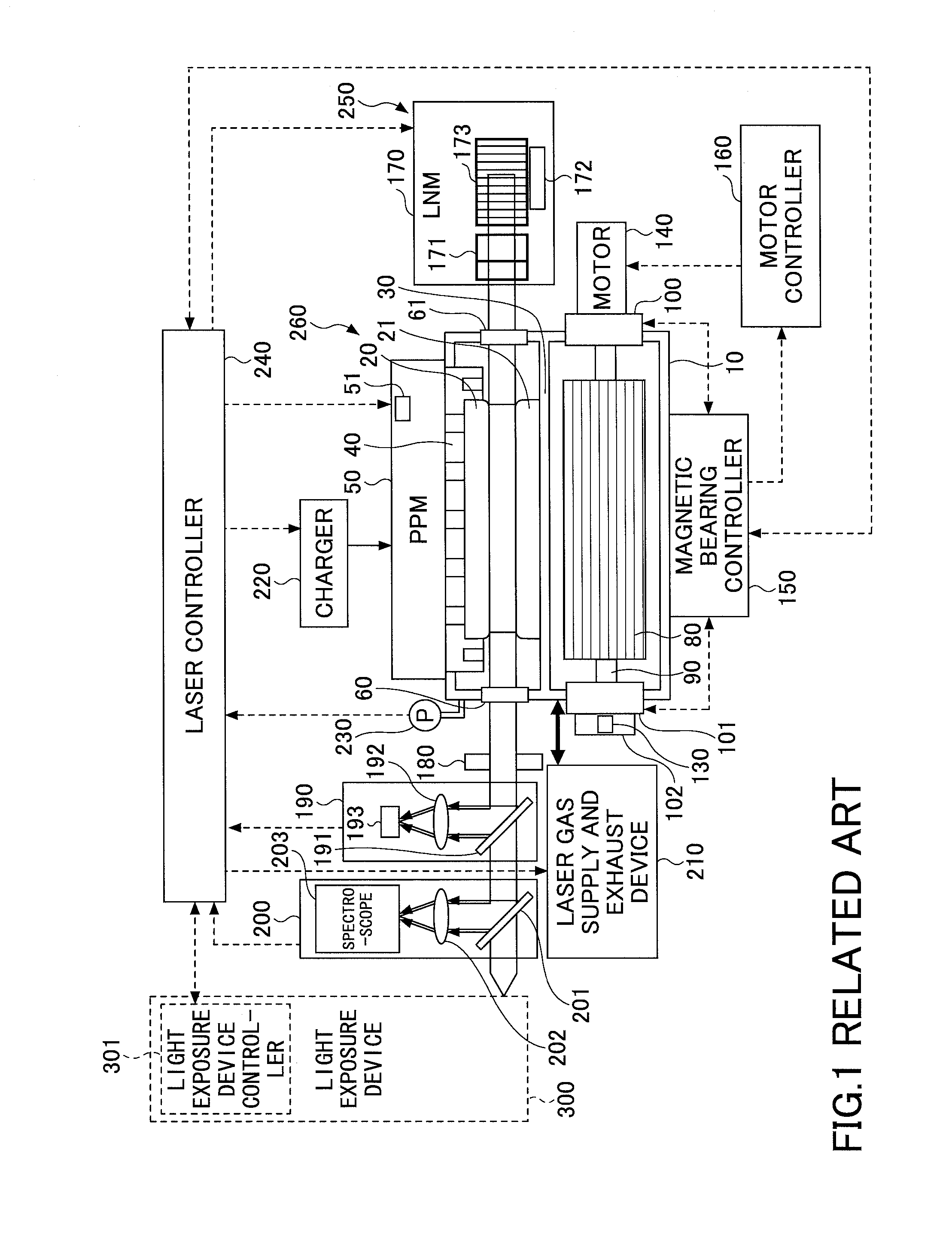
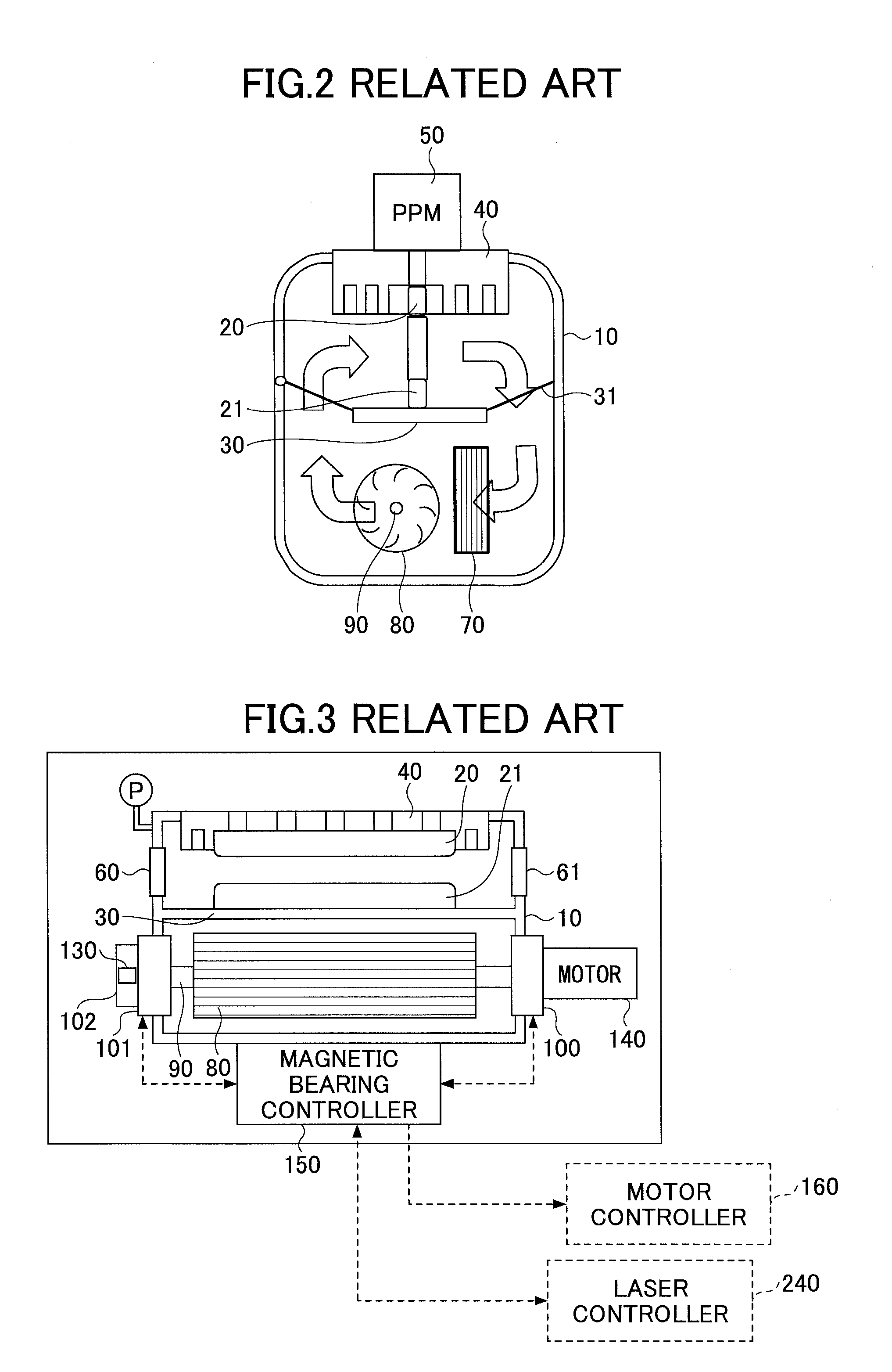
A discharge-pumped gas laser device described in this patent has a laser chamber, two discharge electrodes, a fan with a magnetic bearing, a housing, and a magnetic bearing controller. The device can circulate gas in the chamber and can be controlled by the magnetic bearing controller, separate from the housing. The technical effect of this device is the ability to efficiently and controllably circulate gas in a laser chamber, which can improve laser performance and reliability.

Problems solved by technology

The natural oscillation spectral bandwidth of a KrF or ArF excimer laser device is as wide as 350-400 pm, and thus chromatic aberration will occur if the projection lens in the device is used, leading to a drop in the resolution.

Method used


Image

  • Discharge-pumped gas laser device
  • Discharge-pumped gas laser device
  • Discharge-pumped gas laser device

Examples


Embodiment Construction

[0046]Hereinafter, embodiments of the present disclosure will be described in line with the following contents.

Contents

1. Overview

2. Terms

[0047]3. Excimer laser device

3.1 Configuration

3.2 Operation

3.3 Problem

[0048]4. Excimer laser device including magnetic bearings

4.1 Control flow of a laser controller

4.1.1 Flow at the time of replacement of a laser chamber

4.1.2 Flow for a certain number of shot or a certain period of time

4.1.3 Flow at the time of changing of a laser gas pressure

4.1.4 Flow based on detection of a vibration sensor

4.1.5 Flow based on a value of energy stability

4.1.6 Flow based on a value of wavelength stability

4.1.7 Flow at the time of an error output from a magnetic bearing controller

4.1.8 Flow at the time of touchdown

4.2 Acquisition and setting of control parameters for magnetic bearings

5. Control system for magnetic bearings

6. Calibration of magnetic bearings and acquisition and setting of control parameters

6.1 Calibration of a magnetic bearing sensor

6.2 Calibratio...


PUM


Abstract

A discharge-pumped gas laser device may include a laser chamber, a pair of discharge electrodes provided in the laser chamber, a fan with a magnetic bearing being provided in the laser chamber and configured to be capable of circulating a gas in the laser chamber, a housing configured to contain the laser chamber, and a magnetic bearing controller connected to the magnetic bearing electrically, being capable of controlling the magnetic bearing, and provided in the housing separately from the laser chamber.

Description

CROSS-REFERENCE TO (A) RELATED APPLICATION(S)[0001]The present application claims priority from Japanese Patent Application No. 2012-227584 filed Oct. 15, 2012, the entire contents of which are hereby incorporated by reference.BACKGROUND[0002]1. Technical Field[0003]The present disclosure relates to a discharge-pumped gas laser device.[0004]2. Related Art[0005]The miniaturization and increased levels of integration of semiconductor integrated circuits have led to a demand for increases in the resolutions of semiconductor exposure devices (called “exposure devices” hereinafter). Accordingly, advances are being made in the reduction of the wavelengths of light emitted from exposure light sources. Gas laser devices are being used as exposure light sources instead of conventional mercury lamps. At present, a KrF excimer laser device that emits ultraviolet light at a wavelength of 248 nm and an ArF excimer laser device that emits ultraviolet light at a wavelength of 193 nm are being used...

Claims


Application Information

Patent Timeline
Patent Type & Authority Applications(United States)
IPC IPC(8): H01S3/036H01S3/041
CPCH01S3/041H01S3/036F16C32/047H01S3/02H01S3/223H01S3/2232H01S3/2258
Inventor KUROSU, AKIHIKOFUJIMOTO, JUNICHIISHIZUKA, YOSUKEMATSUNAGA, TAKASHIWAKABAYASHI, OSAMU
Owner GIGAPHOTON
Learn More