
Dental implant

a technology of dental implants and implants, applied in dental implants, dental surgery, medical science, etc., can solve the problems of affecting the success of dental implants, affecting the mechanical strength of the implant and the connection, and affecting the success of the implant, so as to reduce the resorption and gum recession in the critical areas around dental implants. , the mechanical strength of the implant and the connection, and the effect of more bone volum

Active Publication Date: 2014-04-17
MIS IMPLANTS TECH
View PDF18 Cites 39 Cited by
  • Summary
  • Abstract
  • Description
  • Claims
  • Application Information

AI Technical Summary

Benefits of technology

The present invention introduces a modified dental implant head that increases bone volume in crucial areas around the implant. This is done without affecting the remainder of the implant, which maintains its strength. As a result, bone loss and gum recess are reduced, improving dental implant outcomes.

Problems solved by technology

Throughout the history of the art of dental implantology, it has been known that some bone loss and subsequent soft tissue recession always occur and have to be accepted.
However, bone loss still occurs where there is less bone thickness around the implant head.
This effect is most evident, and results in the most disturbing outcome, when it occurs in the thin bone plates buccal to implants placed in the anterior region of the mouth where the tissues are exposed in the smile, as well as between adjacent implants, particularly in the anterior region.
But bone ridge size and implant dimensions may hinder their success.
Similarly, when adjacent implants are required, it may be difficult to leave sufficient space between the implants to permit the required tissue volume.
However, in the anterior maxillary regions, where it may be most desired to access from the lingual (palatal) direction, it is, in many cases, not possible due to the anatomy, size and orientation of the bone ridge (as seen in FIG. 2).

Method used


Image

  • Dental implant
  • Dental implant
  • Dental implant

Examples


Embodiment Construction

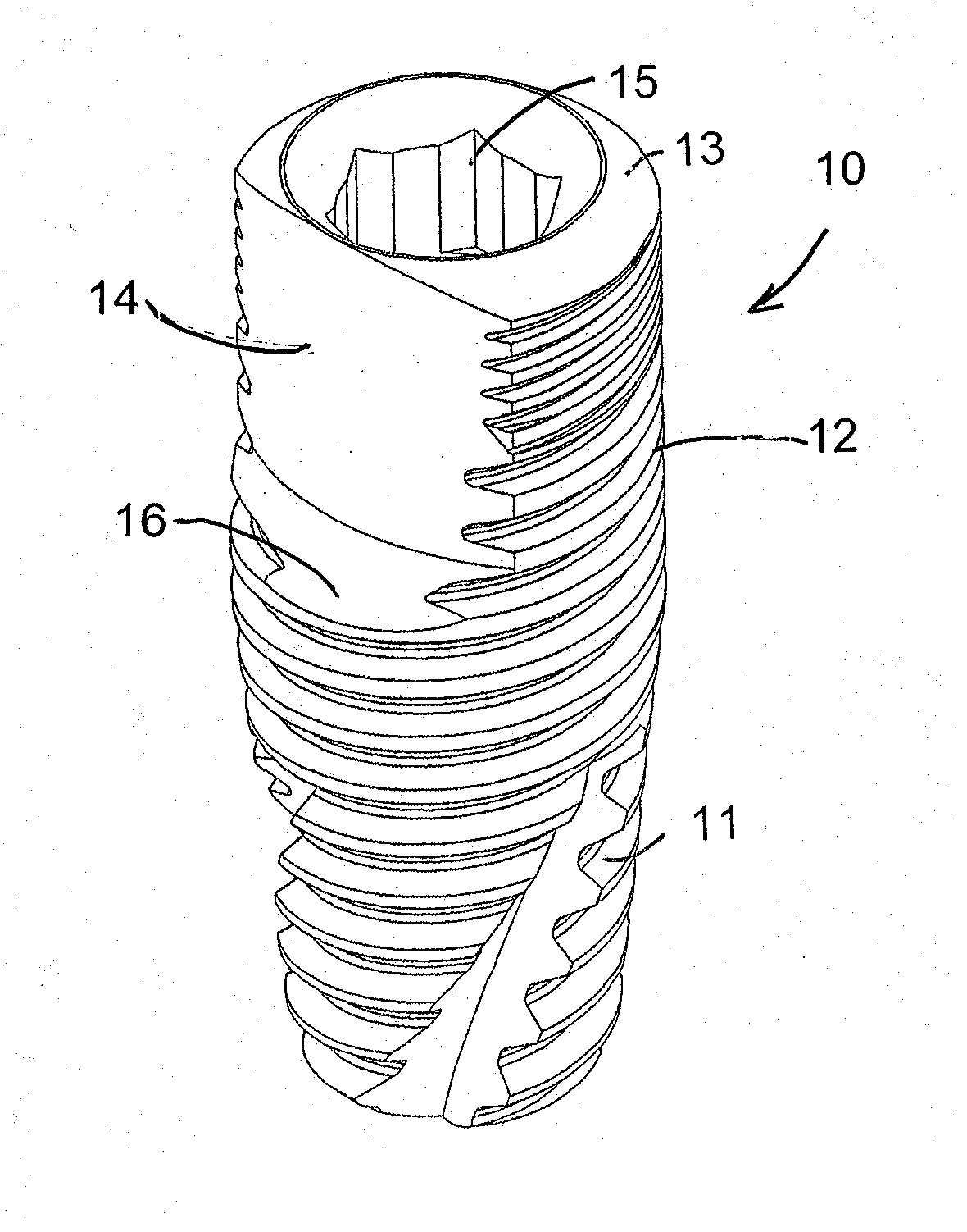
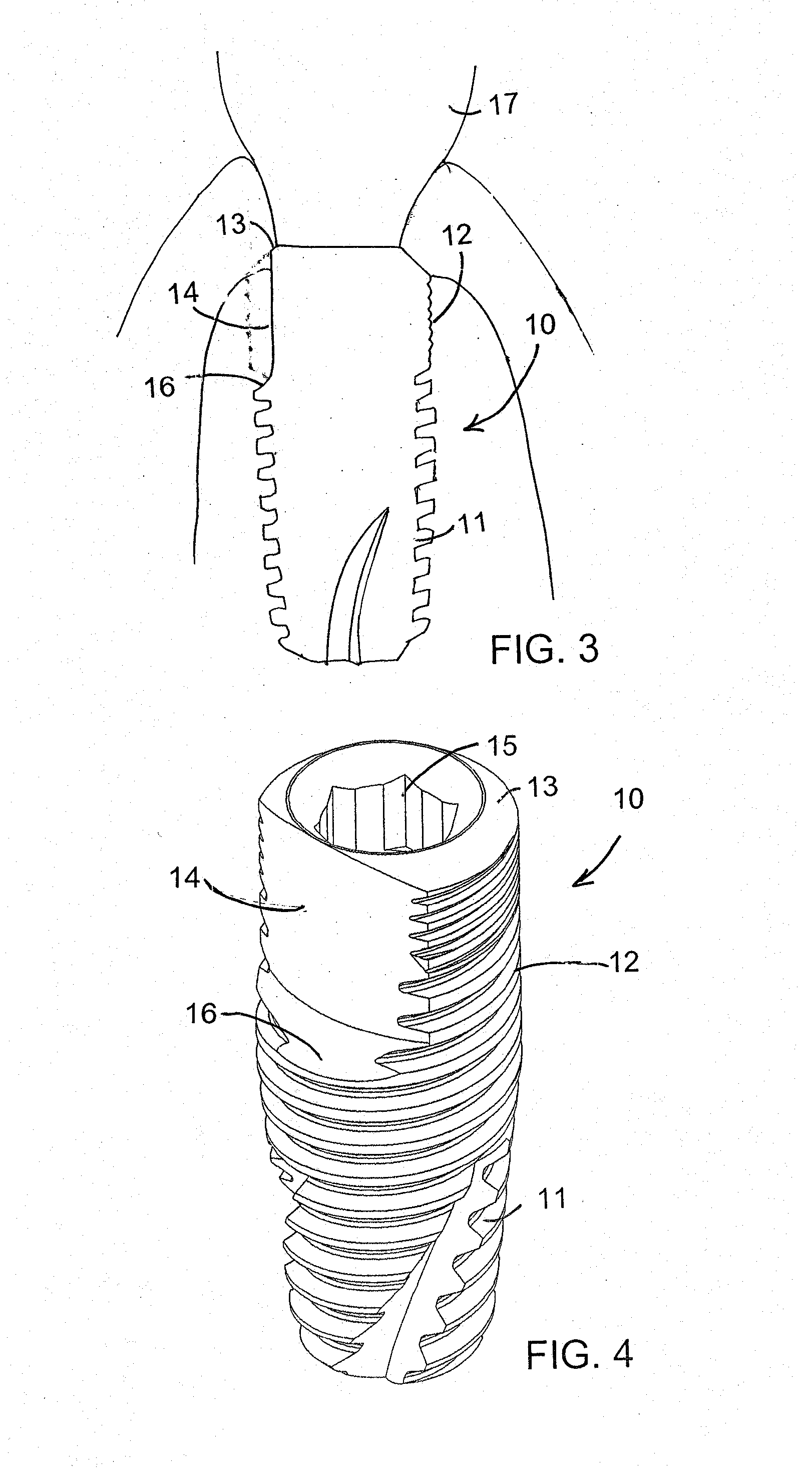
[0034]The present invention relates to a dental implant with a modified head portion that allows more bone in critical locations around the implant head without sacrificing the mechanical strength of the implant and of the connection. An object of the present invention is to reduce bone resorption in critical areas around dental implants by employing this modified design of the head of the implant.

[0035]The new design involves providing an implant having a body and an integrally formed head of substantially smaller periphery than the periphery of the body, where the periphery of the head is not annular. The implant includes an implant body having a top surface from which one or more parts of the circumference of the predominantly tubular shape of the implant body are cut away from the top surface down to a desired height. The flattened surface allows more bone thickness adjacent to it, as compared to an implant having a full contour tubular shape, as the cutaway area becomes filled ...


PUM


Abstract

A dental implant including an implant body having a top surface, and at least one non-annular cutaway portion longitudinally extending downwardly from the top surface along one side of the body and outwardly to the periphery, and a method for making the implant. The implant body preferably includes a body portion and a head portion integrally formed with the body portion, the body portion has a periphery and the head portion has a non-circular periphery, and the periphery of the head portion is smaller than the periphery of the body portion.

Description

FIELD OF THE INVENTION[0001]The present invention relates to the field of dental implants and, more particularly, to the design of the implant's head that maximizes long term stability of the hard and soft tissues surrounding the implant, the abutment and the prosthesis connected to it.BACKGROUND OF THE INVENTION[0002]Dental implants are used to replace teeth that have been lost. An implant is placed in the jaw bone at the site of the missing tooth and a dental prosthetic unit is attached to it. The long term functional and aesthetic success of dental implants, and the prostheses attached to them, is determined by the response of the hard and soft tissues around them. Throughout the history of the art of dental implantology, it has been known that some bone loss and subsequent soft tissue recession always occur and have to be accepted.[0003]In recent years, it has been shown that bone loss and soft tissue loss can be lessened by improving the tissue environment around the head of th...

Claims


Application Information

Patent Timeline
IPC IPC(8): A61C8/00A61C8/02
CPCA61C8/0075A61C8/0006A61C8/0022A61C8/0068A61C8/0018A61C8/0066A61C8/0069A61C8/0077A61C8/0019A61C8/0074
Inventor JACOBY, YUVALBICHACHO, NITZAN
Owner MIS IMPLANTS TECH
Learn More