Sensing catheter emitting radiant energy

Inactive Publication Date: 2014-04-17
PERCUVISION
View PDF1 Cites 38 Cited by
  • Summary
  • Abstract
  • Description
  • Claims
  • Application Information

AI Technical Summary

Benefits of technology

[0009]The present invention alleviates the current problems in packaging additional functionality in small diameter, tapered tip catheters and other similar medical instruments. It does this by a design that permits shared simultaneous use of a common shared cross sectional area in t

Problems solved by technology

To fit this into the confines of a small diameter instrument with tapered entry section poses a major challenge.
This has made it difficult to combine desired functionality.
However, the very restricted dimensions that are permissible in for instance urinary catheters, make it very challenging to fit even a state of the art subminiature camera and required additional functionality in the instrument tip.
These have the disadvantage of high cost due to the precision sorted arrangement of fibers in both ends.
They have also the particular disadvantage of poor image resolution in small diameter applications due to the limited number of fibers that can be fitted in a small cross section.
This limits the image clarity for the operator and may result in more difficult

Method used


Image

  • Sensing catheter emitting radiant energy
  • Sensing catheter emitting radiant energy
  • Sensing catheter emitting radiant energy

Examples


Embodiment Construction

[0052]This invention is best described by reference to each figure of the Drawing.

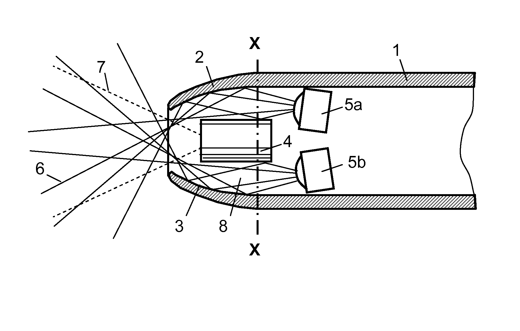
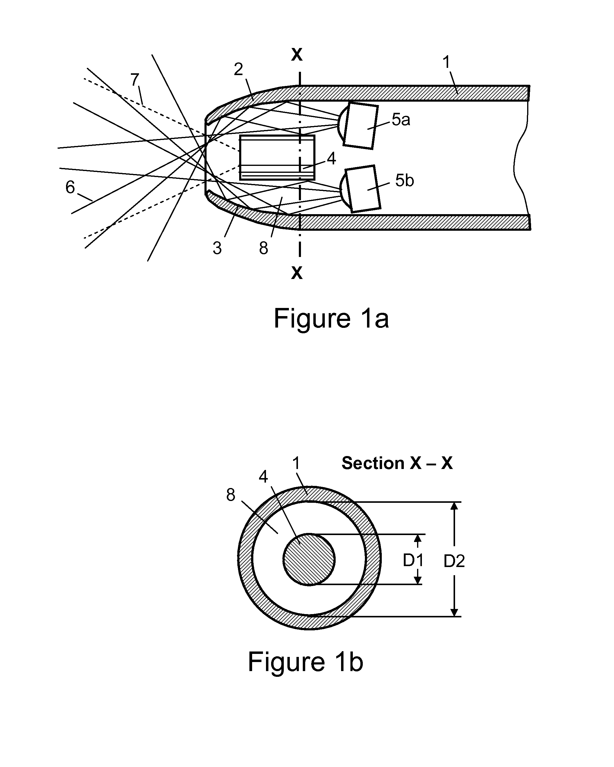
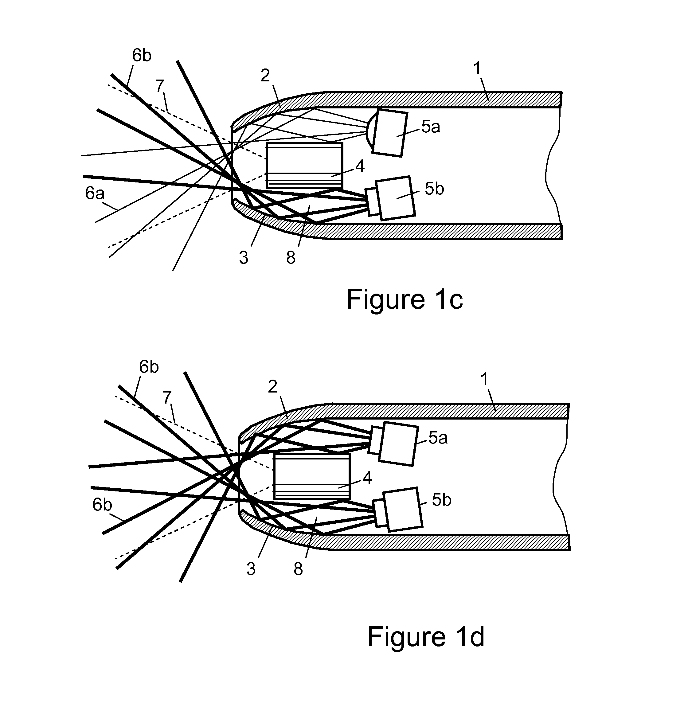
[0053]In FIG. 1a is illustrated the principle of the employment of the sensing system with a fluid channel. A catheter sleeve 1 has a tapered tip 2 for less traumatic and safer entry in patient lumen or narrow passages. On the interior side of the tip 2 is reflective surface 3 that directs the light or treatment radiation from one or more sources 5a, 5b into the patient, while passing around the camera 4 placed inside the tip 2. The sources 5a and 5b may be LEDs or lasers. By placing the sources behind the camera, space is gained for allowing larger components. The camera 4 may furthermore have a reflective exterior to improve illumination light guiding. The reflective surface 3 may have mirror finish or diffuse characteristics to achieve desired light patterns. The annular passage 8 between the camera 4 and the tip 2 may optionally also function as a fluid channel passing fluid or gas the same way as ...


PUM


Abstract

A sensing catheter having an outer flexible sheath and a proximal section containing a sensing system having a sensing means, a radiant energy providing means and radiation transmitting means, preferably all housed within a fluid channel.

Description

[0001]This application is a Continuation-in-Part application of U.S. Ser. No. 14 / 124,435, filed Dec. 6, 2013, as a National Stage Entry application of PCT / US2012 / 040877, filed Jun. 5, 2012, which is a non-provisional application which claims benefit of U.S. Provisional Application 61 / 493,521, filed Jun. 6, 2011.BACKGROUND OF THE INVENTION[0002]This invention is in the technical field of medical instruments, in particular for sensing, especially vision equipped, catheters, for insertion in narrow body lumens or passages. As an example, urinary catheters with vision and / or other sensing devices have to fit within the very narrow confines and thin fragile walls of the urethra.[0003]In a first consideration, this requirement drives such instruments to have a very small cross section and a well tapered entry portion at the tip to allow safe insertion with minimum patient discomfort or risk for procedure complications.[0004]But in a second consideration, there are also major benefits to i...

Claims


Application Information

Patent Timeline
IPC IPC(8): A61B5/00A61B1/07A61M25/00A61B6/00
CPCA61B5/0086A61B6/425A61M25/003A61B1/07A61B5/6852A61B1/00096A61B1/00135A61B1/015A61B1/05A61B1/0607A61B1/0676A61B1/0684A61B1/307A61B5/0071A61B5/0075A61B5/015A61B5/0507A61B6/4057A61B18/1492A61B18/24A61B2018/00982A61B2018/1861A61B2018/2272A61N5/045A61N5/0601A61N2005/0666G02B23/2461G02B23/2484A61B2018/2211
Inventor HELLSTROM, AKE A.SINGH, ERROL O.
Owner PERCUVISION
Why Eureka
Try Eureka