Protection against spill and syringe related contamination

a technology of syringe and plunger, which is applied in the direction of intravenous devices, infusion needles, other medical devices, etc., can solve the problems of inadvertent rotation of the associated syringe rather than the grasping of the connector adapter, and the inability to uncover the associated syringe to undesirable external exposure, etc., to achieve reliable and effective effect, robust

Inactive Publication Date: 2014-04-17
THORNE JR GALE H +1
View PDF2 Cites 0 Cited by
  • Summary
  • Abstract
  • Description
  • Claims
  • Application Information

AI Technical Summary

Benefits of technology

[0023]Continuously affixed to and proximally disposed from the distally disposed portion is an elongated portion which is preferably at least as long as plunger displacement distance within the syringe barrel. Disposed proximally from the elongated portion is a portion having an expanded girth whereby the expanded portion can be disposed about flanges of the syringe without undue material stress after being so disposed. Proximal from the expanded portion, the barrier tube comprises a rolled section (similar the mouth of a balloon) which circumscribes an open mouth, the mouth being sized to fit snugly about an associated syringe barrel to provide a treacherous path against cross communication of b...

Problems solved by technology

When that interface is inadvertently opened, resulting drug spills are often considered very dangerous.
However, experience has shown that inadvertent rotation of an associated syringe rather than grasping the connector adapter can occur and when stiction (force required to overcome static friction and initiate motion) of the syringe/connector adapter interface is less than stiction of the needleless connector/connector adapter interface.
In such a case, the syringe can be resultingly disengaged from the connector adapter providing opportunity for a spill.
In practice, it has been found that wear during use and storage, changes in material due to aging and sterilization procedures and stress associated with stretching such material about flanges of an associated syringe can result in material failure in tubes of substantially constant diameter and thickness r...

Method used


Image

  • Protection against spill and syringe related contamination
  • Protection against spill and syringe related contamination
  • Protection against spill and syringe related contamination

Examples


Embodiment Construction

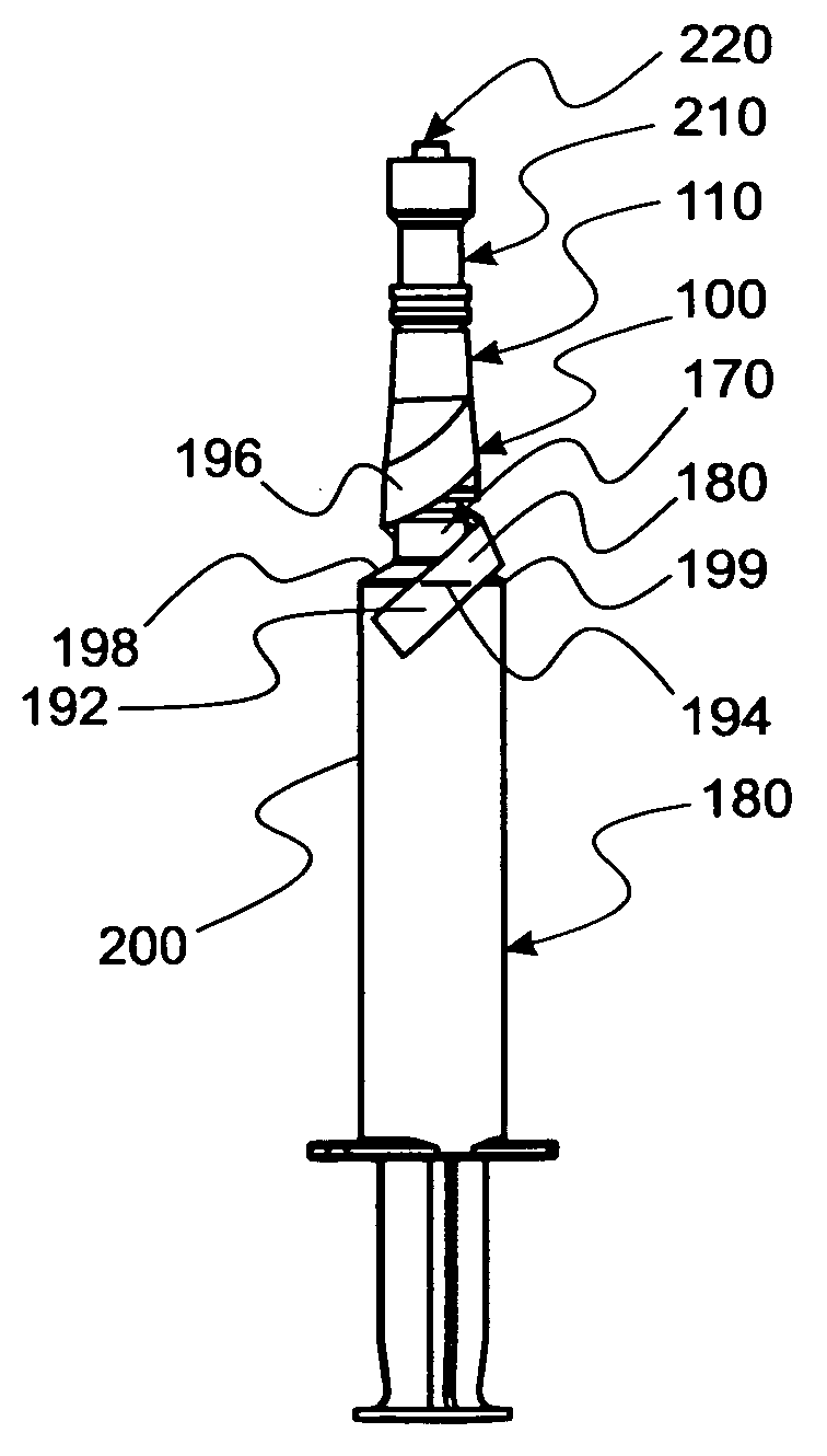
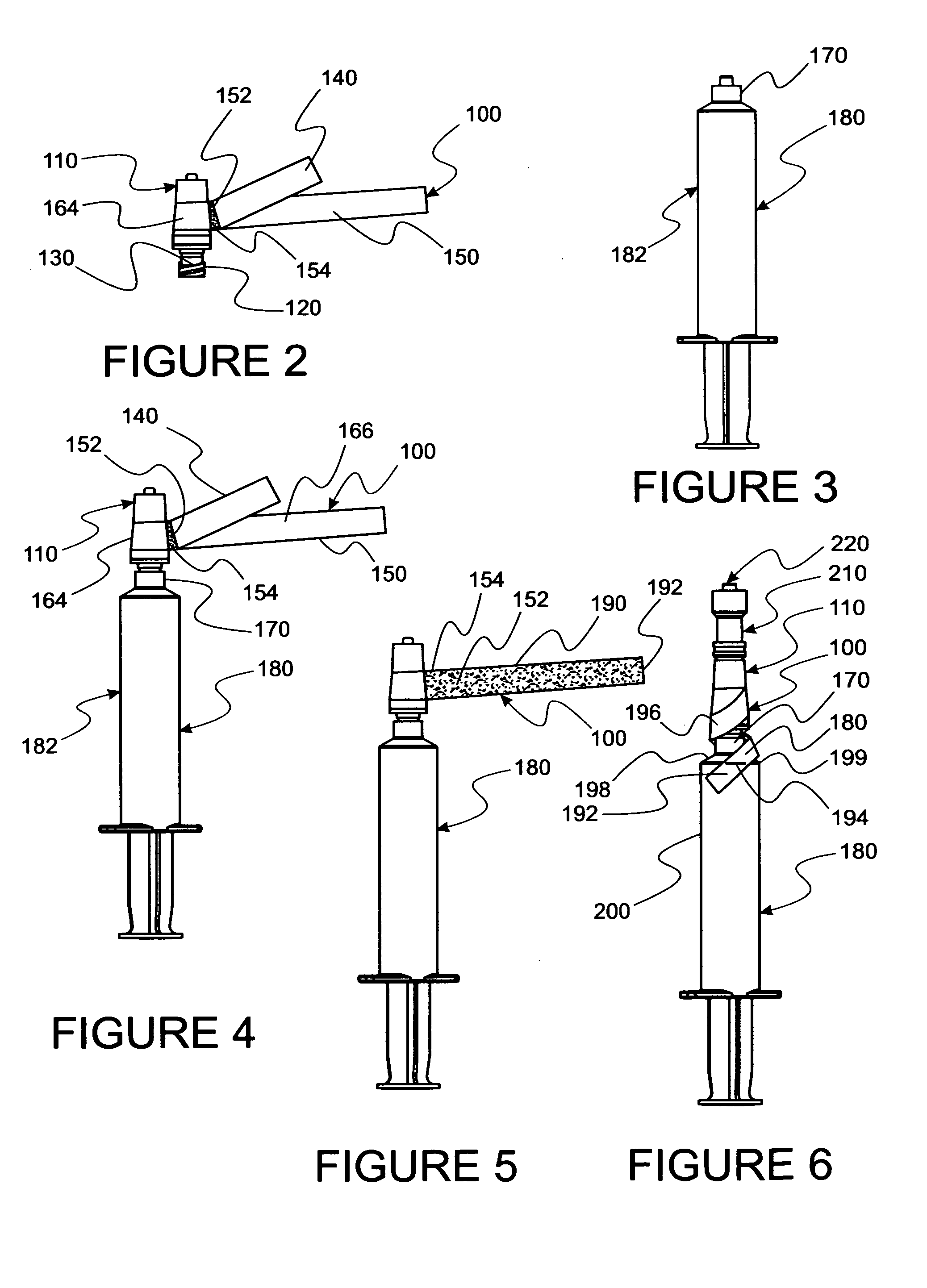
[0047]In this disclosure, the term proximal is used to indicate the segment of the device normally closest to the object of the sentence describing its position. The term distal refers to the other end. Reference is now made to the embodiments illustrated in FIGS. 1-16 wherein like numerals are used to designate like parts throughout. Primes of numbers are used to designate similar, but not identical, parts.

Safety Strap

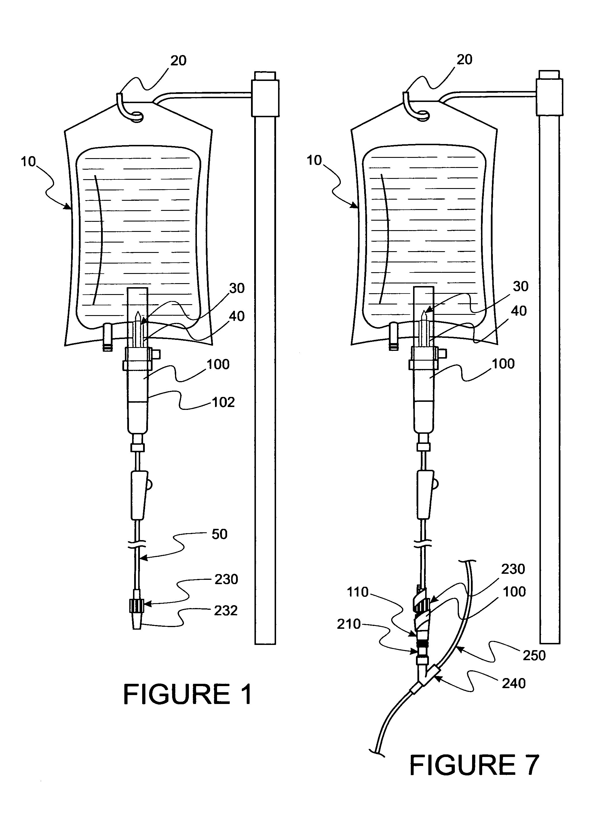
[0048]Referencing FIGS. 1-7, a spiked bag 10 is seen hung from an elevated hook 20 in FIG. 1. A spike 30 is inserted through a bag port 40. Spike 30 is affixed as part of a secondary IV set 50. Such sets are currently commercially provided in many different configurations for delivery of fluids from a bag 10 to a patient.

[0049]To reduce likelihood of inadvertent disengagement of spike 30 from port 40 an adhesive strap 100 is adhesively affixed to bag 10 and a proximal portion 102 of set 50. So disposed, force required to disengage spike 30 from port 40 is measurably i...


PUM


Abstract

Methods and apparatus for employing an adhesive strap about a medical connection for improving connection integrity for greater safety and reliability and a cross contamination barrier for medical syringes is disclosed. Also, a shielding tube for a medical syringe which acts as a barrier against cross contamination across a syringe plunger is disclosed. The tube comprises a pattern of raised ribs inside to protect against potentially tube tearing edges of an associated plunger rod assembly and to provide a skid resistant surface when disposed about flanges of the syringe.

Description

CONTINUATION IN PART[0001]This Patent Application is a CONTINUATION-IN-PART of a Provisional U.S. Patent Application 61 / 699,963 filed by Gale H. Thorne, et al. (Thorne 963). Sep. 12, 2012 and titled PROTECTION AGAINST SPILL AND SYRINGE RELATED CONTAMINATION which is a CONTINUATION-IN-PART of U.S. patent application Ser. No. 13 / 066,565 filed by Gale H. Thorne, et al. Apr. 18, 2011, and titled MEDICAL SYRINGE PRIME AND CROSS CONTAMINATION FREE DEVICES which are made part hereof by reference.FIELD OF INVENTION[0002]This invention relates to medical connections and syringe plunger interfaces whereat inadvertent spills and cross contamination can occur.BACKGROUND AND RELATED ART[0003]When dealing with syringes, generally two modes of concern, i.e. spills and cross contamination should be considered. The first, being of greatest concern in oncology and other hazardous drug handling, deals with spills which may occur at a luer connecting interface, e.g. at the connecting end of a syringe. ...

Claims


Application Information

Patent Timeline
IPC IPC(8): A61M5/00
CPCA61M5/001A61M39/10A61M39/16A61M39/18A61M2039/1066A61M2039/1077
Inventor THORNE, JR., GALE H.THORNE, KENDALL P.
Owner THORNE JR GALE H
Why Eureka
Try Eureka