Method for positioning a transfer unit, method for calculating positional deviation amount of an object to be processed, and method for correcting teaching data of the transfer unit

a transfer unit and amount technology, applied in the direction of electric programme control, program control, instruments, etc., can solve the problems of large deviation between operators, difficulty in checking contact state with naked eyes, deteriorating operation efficiency, etc., to improve teaching operation working efficiency, reduce deviation, and reduce interference.

Active Publication Date: 2014-04-17
TOKYO ELECTRON LTD
View PDF6 Cites 18 Cited by
  • Summary
  • Abstract
  • Description
  • Claims
  • Application Information

AI Technical Summary

Benefits of technology

[0013]In view of the above, the present invention provides a transfer unit positioning method capable of reducing deviation between operators by improving a working efficiency of a teaching operation and reducing a possibility of interference between a pick and an object to be processed, a method for calculating a positional deviation amount of the object and a method for correcting teaching data of the transfer unit.

Problems solved by technology

In the above positioning method, since the mounting pad is brought into contact with a backside of the wafer W, it is difficult to check the contact state with naked eyes and deviation between operators is large.
In order to install a wafer at a teaching position, a ceiling cover of the apparatus which corresponds to the teaching position needs to be opened, which may operation efficiency deteriorates.
In JP2006-185960A, a Z-axis (vertical direction) teaching jig is additionally required, which is troublesome.
Further, when the pick is made to access each of the substrate support pins, an operator should perform the access operation with naked eyes and a working efficiency deteriorates.

Method used


Image

  • Method for positioning a transfer unit, method for calculating positional deviation amount of an object to be processed, and method for correcting teaching data of the transfer unit
  • Method for positioning a transfer unit, method for calculating positional deviation amount of an object to be processed, and method for correcting teaching data of the transfer unit
  • Method for positioning a transfer unit, method for calculating positional deviation amount of an object to be processed, and method for correcting teaching data of the transfer unit

Examples


first embodiment

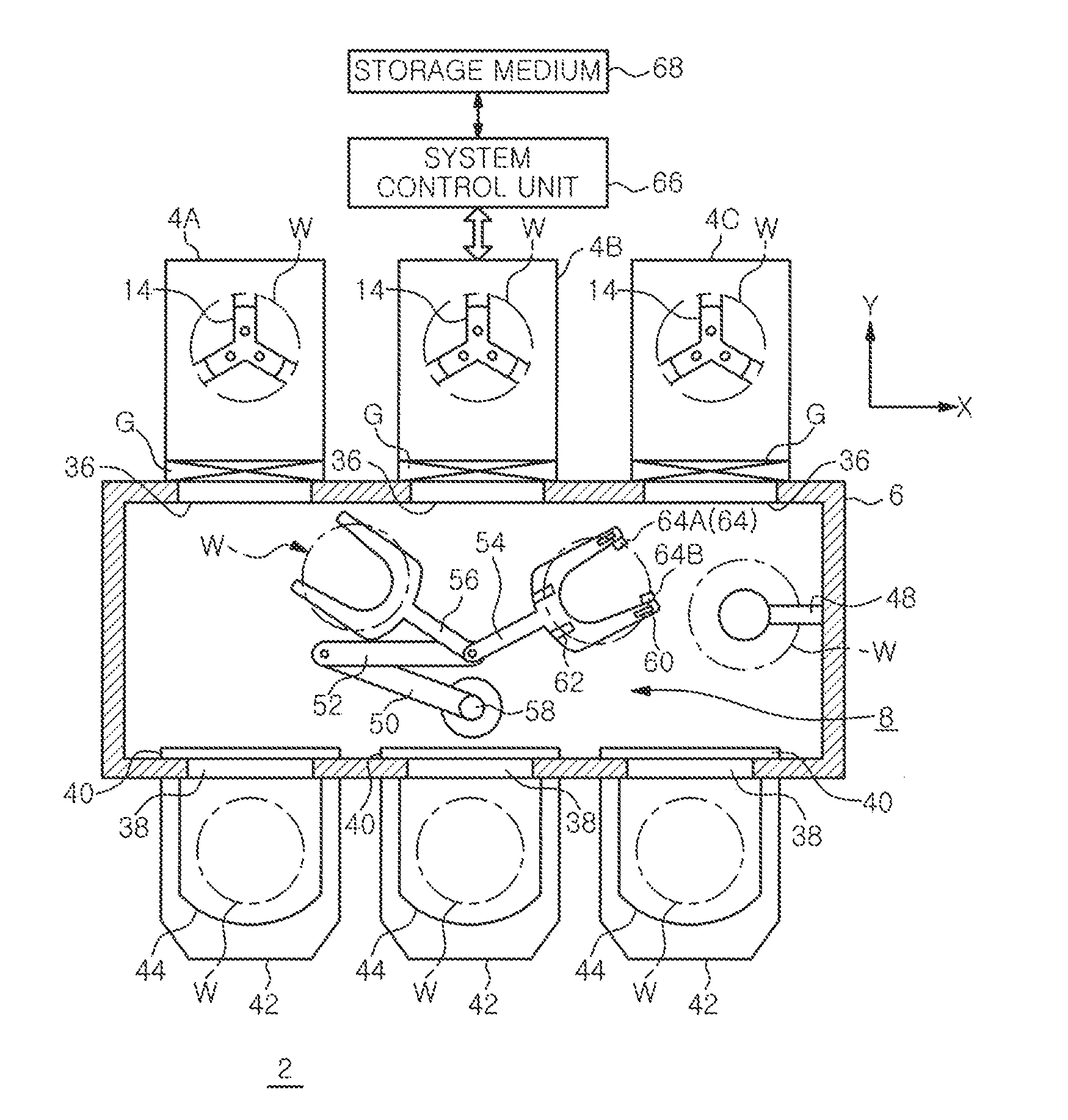
[0069]First, the first embodiment of the method for determining a position of a transfer unit will be described.

[0070]In the teaching operation performed when the picks 54 and 56 of the transfer unit 8 are made to access the mounting table 14, the relative positional relationship between the picks 54 and 56, and the support arms 18 and the support pins 20 of the mounting table 14 needs to be determined on the coordinates. To do so, it is required to obtain the height positions of the picks 54 and 56, the forward-moving angles of the picks 54 and 56 which avoids interference between the picks 54 and 56 and the periphery of the gate opening 36, the positions in the X direction, and the forward moving amount (length), i.e., the moving amount in the Y direction, of the picks 54 and 56 during forward movement. Here, for convenience, the length direction of the atmospheric transfer chamber 6 is set to the X direction; the direction directed from the atmospheric transfer chamber 6 toward t...

second embodiment

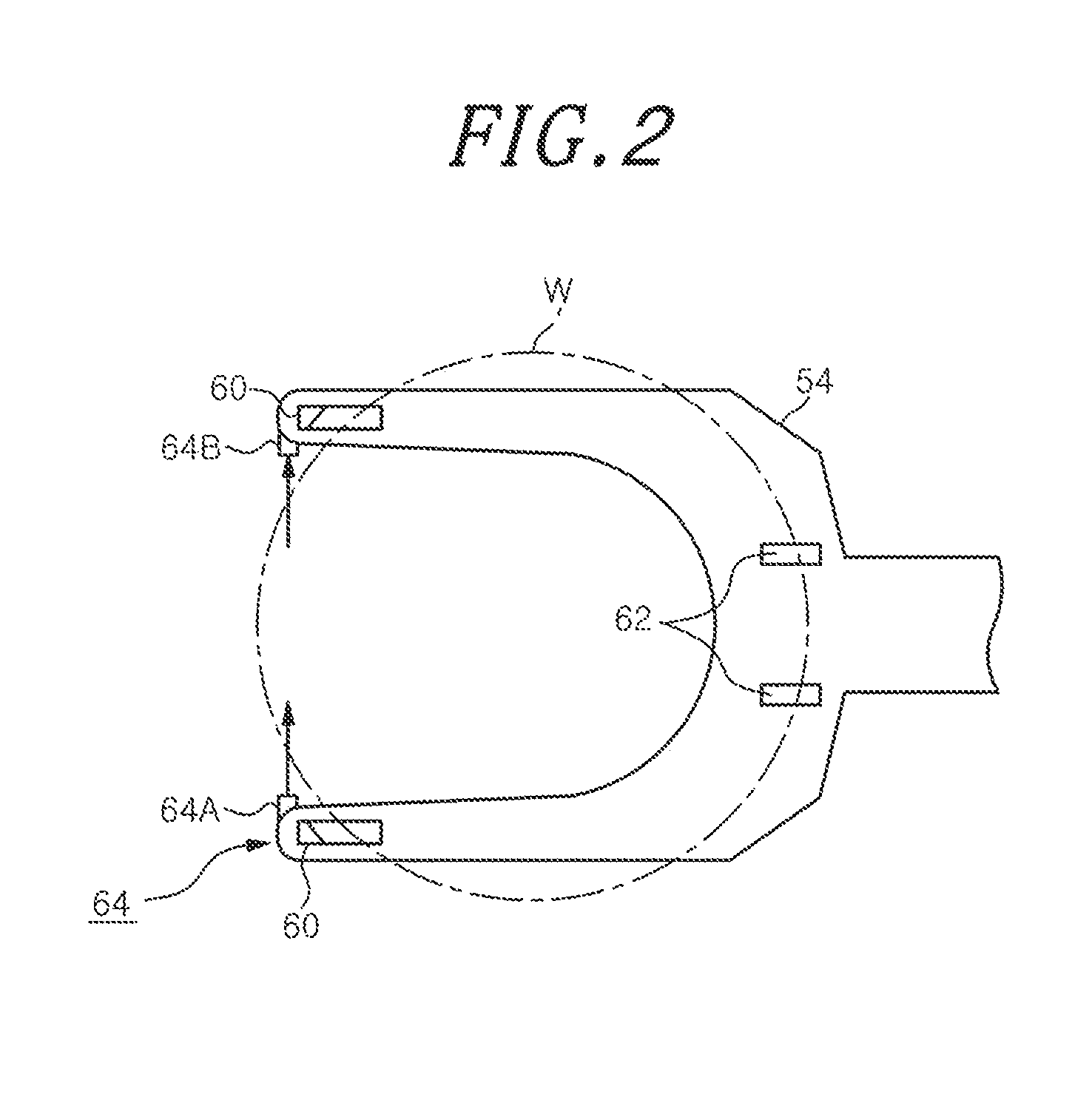
[0110]Hereinafter, the second embodiment of the method for positioning a transfer unit of the present embodiment will be described. In the first embodiment, the relative positional relationship between the pick 54 and the support pin 20 has been determined. However, in the second embodiment, the relative positional relationship between the pick and the intermediate pin 22 (see FIG. 3) as well as the support pin 20 is obtained to perform the teaching operation.

[0111]First, as shown in FIG. 14, the second embodiment of the method for positioning a transfer unit includes: a height position determining process that is the same as the height determining process of the first embodiment (see FIG. 4); a first coordinate determining process of obtaining first coordinates that are coordinates of the support pin 20 about the rotation center of the pick 54; a second coordinate determining process of obtaining second coordinates that are coordinates of the intermediate pin 22 about the rotation ...


PUM


Abstract

In a method for positioning a transfer unit including, support pins for supporting object, and a pick having at a leading end thereof a detection unit for detecting presence or absence of the object, a height reference position of the pick is determined by detecting an upper edge of one of the support pins by the detection unit. A forward moving angle of the pick is corrected by obtaining a deviation angle between a radial direction of the mounting table passing through the corresponding support pin and a forward moving direction of the pick. A forward movement starting point of the pick is corrected by obtaining a horizontal deviation distance between the radial direction of the mounting table and the forward moving direction of the pick. A forward moving reference amount of the pick is obtained from coordinates of the corresponding support pin.

Description

CROSS-REFERENCE TO RELATED APPLICATIONS[0001]This application claims priority to Japanese Patent Application No. 2012-279632 and 2012-228077 filed on Dec. 21, and Oct. 15, 2012, the entire contents of which are incorporated herein by reference.FIELD OF THE INVENTION[0002]The present invention relates to a method for positioning a transfer unit for transferring an object to be processed such as a semiconductor wafer or the like, a method for calculating a positional deviation amount of the object to be processed, and a method for correcting teaching data of the transfer unit.BACKGROUND OF THE INVENTION[0003]Generally, various processes such as film formation, etching, oxidation, diffusion and the like are performed on a wafer to manufacture a semiconductor integrated circuit. For example, Japanese Patent Application Publication No. 2000-208589 discloses a processing system in which a plurality of processing apparatuses for performing the same process or different processes is connect...

Claims


Application Information

Patent Timeline
Patent Type & Authority Applications(United States)
IPC IPC(8): G05B19/418
CPCG05B19/4189G05B2219/37608H01L21/67259H01L21/67748H01L21/67766H01L21/681H01L21/67265H01L21/67742G05B2219/39527G05B2219/45031
Inventor KUBODERA, MASATOKIKUSHIMA, HIROHITOYAMAGUCHI, HIROFUMISASAKI, YOSHIAKIYU, MENG YIAU
Owner TOKYO ELECTRON LTD
Why Eureka
Try Eureka