System and method for providing a reflective insulation layer

a reflective insulation and layer technology, applied in the field of insulation layers, can solve the problem that the layer of conventional reflective insulation systems does not structurally accommodate vapor transmission, and achieve the effect of not facilitating the growth of mold

Inactive Publication Date: 2014-04-24
FI FOIL
View PDF4 Cites 2 Cited by
  • Summary
  • Abstract
  • Description
  • Claims
  • Application Information

AI Technical Summary

Problems solved by technology

Additionally, the layers of conventional reflective insulation systems do not structurally accommodate vapor transmission, without perforations through all the layers.

Method used


Image

  • System and method for providing a reflective insulation layer
  • System and method for providing a reflective insulation layer
  • System and method for providing a reflective insulation layer

Examples


Embodiment Construction

[0014]In describing particular features of different embodiments of the present invention, number references will be utilized in relation to the figures accompanying the specification. Similar or identical number references in different figures may be utilized to indicate similar or identical components among different embodiments of the present invention.

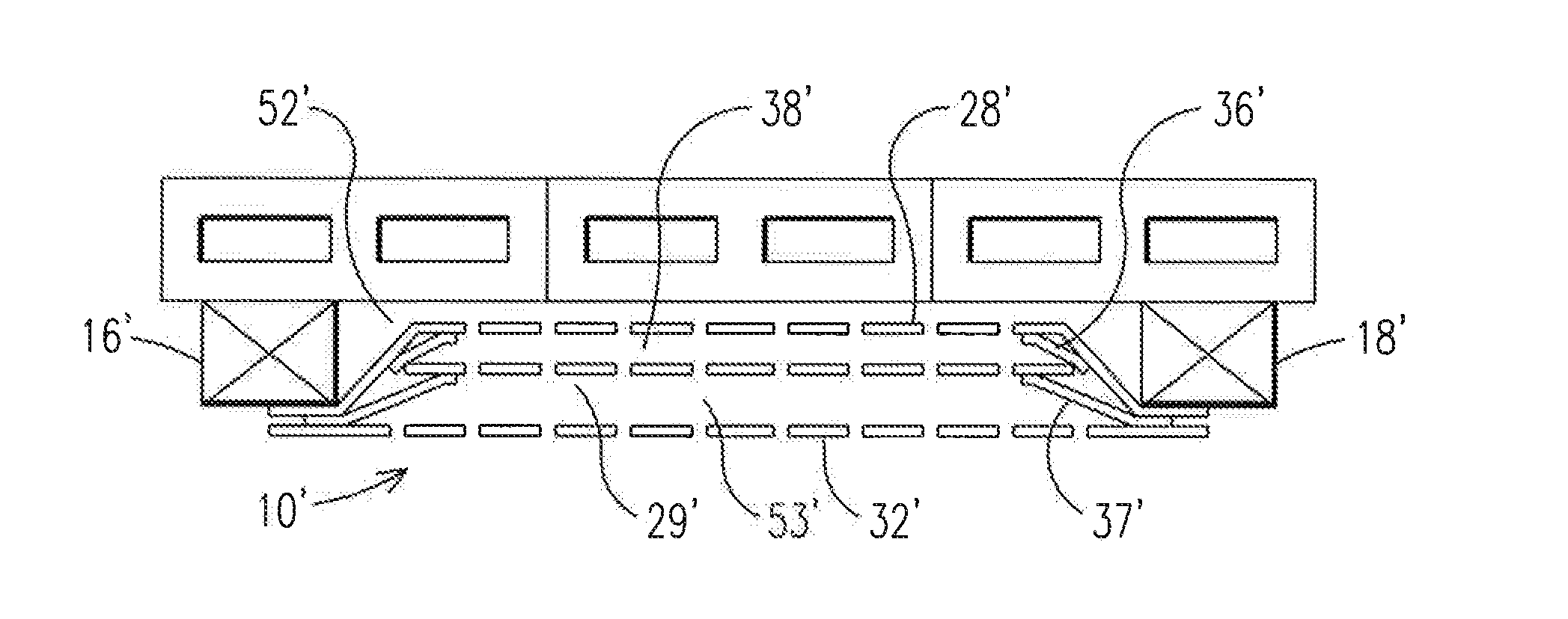
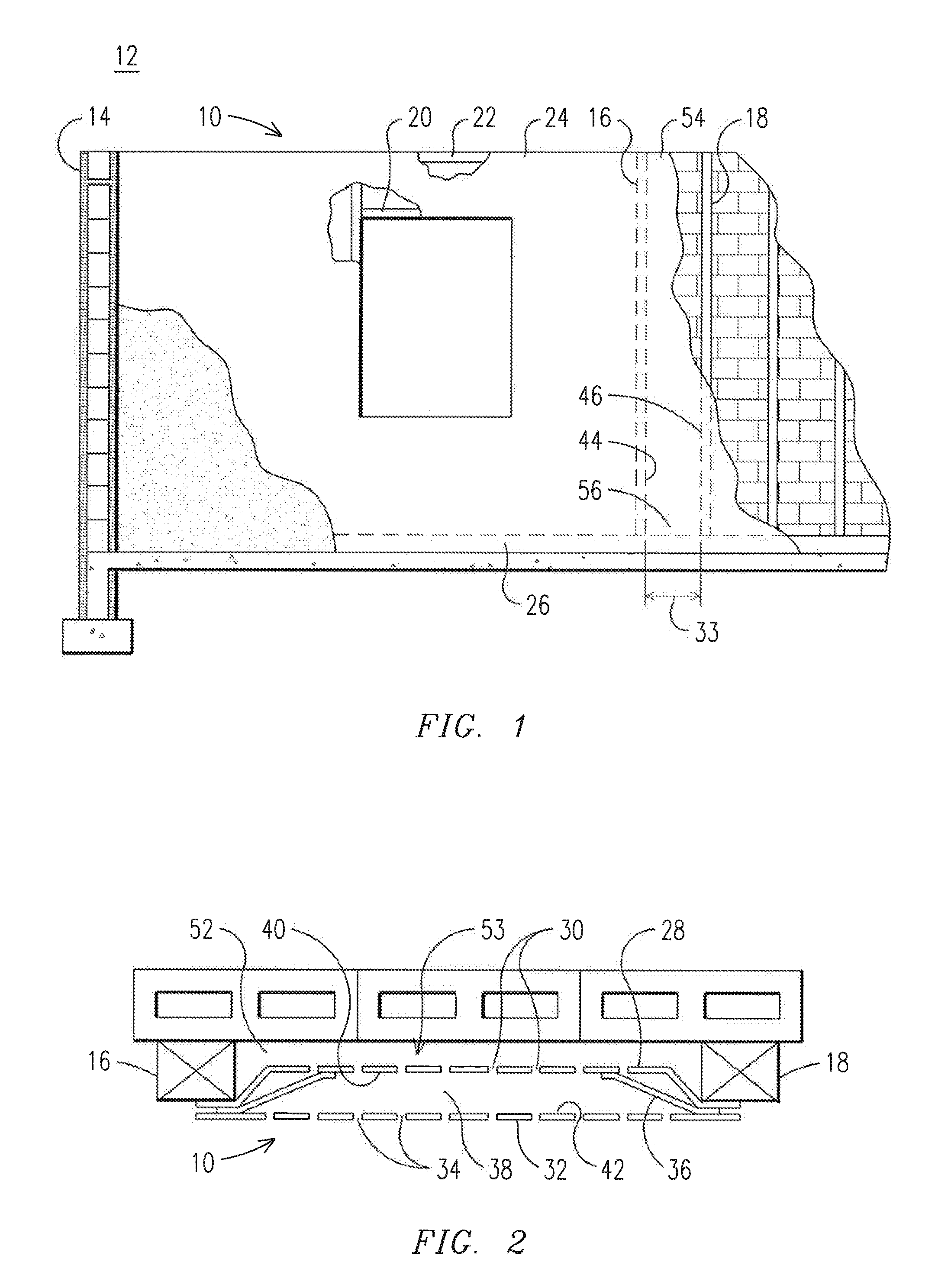
[0015]FIG. 1 illustrates a reflective insulation layer 10 for a structure 12. The structure 12 includes a wall 14 with a plurality of horizontally spaced-apart strips (or vertically oriented) 16,18 and vertically spaced apart strips (or horizontally oriented) 20,22. The horizontally spaced-apart strips 16,18 extend along the wall 14 from a top portion 24 of the wall 14 to a bottom portion 26 of the wall 14. In an exemplary embodiment, the horizontally spaced-apart strips 16,18 and / or vertically spaced-apart strips may be spaced by 16″ or 24″, as appreciated by one of skill in the art. Although FIG. 1 illustrates that the wall 14 in...


PUM

PropertyMeasurementUnit
elongationaaaaaaaaaa
TD heat shrinkageaaaaaaaaaa

Abstract

A reflective insulation layer is provided for a structure. The structure includes a wall and spaced-apart strips which extend along the wall from a top portion of the wall to a bottom portion of the wall. The reflective insulation layer includes a low emittance layer having first perforations, an intermediate low emittance layer having first perforations and an outer synthetic polymer layer having second perforations. Additionally, the reflective insulation layer includes a first expander spaced between the low emittance layer and the intermediate low emittance layer, to couple the low emittance layer to the intermediate low emittance layer and form a first air space. Additionally, the reflective insulation layer includes a second expander spaced between the intermediate low emittance layer and the outer synthetic polymer layer, to couple the intermediate low emittance layer to the outer synthetic polymer layer and form a second air space.

Description

CROSS-REFERENCE TO RELATED APPLICATIONS[0001]This application is a Divisional Application that claims the benefit of U.S. Non-Provisional patent application Ser. No. 12 / 503,493, filed Jul. 15, 2009 and U.S. Provisional Patent Application No. 61 / 080,719, filed Jul. 15, 2008, which are both incorporated herein by reference.BACKGROUND OF THE INVENTION[0002]The present invention relates to insulation layers, and more particularly, to a system and method for providing reflective insulation layers.[0003]Thermal insulation is an important characteristic of most residential, commercial, agricultural, and industrial building structures, including residences. Conventional thermal insulation systems include reflective insulation technology, which attempts to reflect heat energy back to the atmosphere and / or not emit heat energy into a structure during the summer. Additionally, this conventional reflective insulation technology attempts to reflect heat energy back into the structure and / or not ...

Claims


Application Information

Patent Timeline
Patent Type & Authority Applications(United States)
IPC IPC(8): E04B1/76
CPCE04B1/7612E04B1/7654E04B1/76E04B2001/7691Y10T29/49826Y10T428/24752
Inventor LIPPY, WILLIAM A.BASSHAM, ADDRIC E.KINNINGER, DOUGLAS F.PRICE, CRAIG T.SWANSON, ROBERT L.SHERIDAN, JAMES T.
Owner FI FOIL
Why Eureka
Try Eureka