Stress reduction components for sensors

a technology of stress reduction and components, applied in the direction of speed/acceleration/shock measurement, measurement devices, instruments, etc., can solve problems such as worsening of sensor errors, reduce stress on sensor components, reduce stress on sense elements, and increase accuracy over temperature

Active Publication Date: 2014-04-24
HONEYWELL INT INC
View PDF12 Cites 8 Cited by
  • Summary
  • Abstract
  • Description
  • Claims
  • Application Information

AI Technical Summary

Benefits of technology

[0007]The present invention reduces stress on the sensor resulting from temperature extremes and multiple coefficients of thermal expansion and also to assist in maintaining co-axiality between sense elements and the return path. The present invention is particularly useful for down hole use where the environment requires use of materials with non-ideal coefficient of thermal expansion match. The present invention reduces the stress on the sense element, increasing accuracy over temperature by including flexure(s) for the mounting points between the sense element and the return path of a quartz flexure accelerometer. The arrangement of the flexures not only reduces stress but assists in maintaining co-axiality between the sense element and the return path.

Problems solved by technology

Additionally, any slip of the mounting points causes error.
Any one of these, or a combination thereof, will cause sensor error that is made worse by temperature extremes.

Method used


Image

  • Stress reduction components for sensors
  • Stress reduction components for sensors
  • Stress reduction components for sensors

Examples


Embodiment Construction

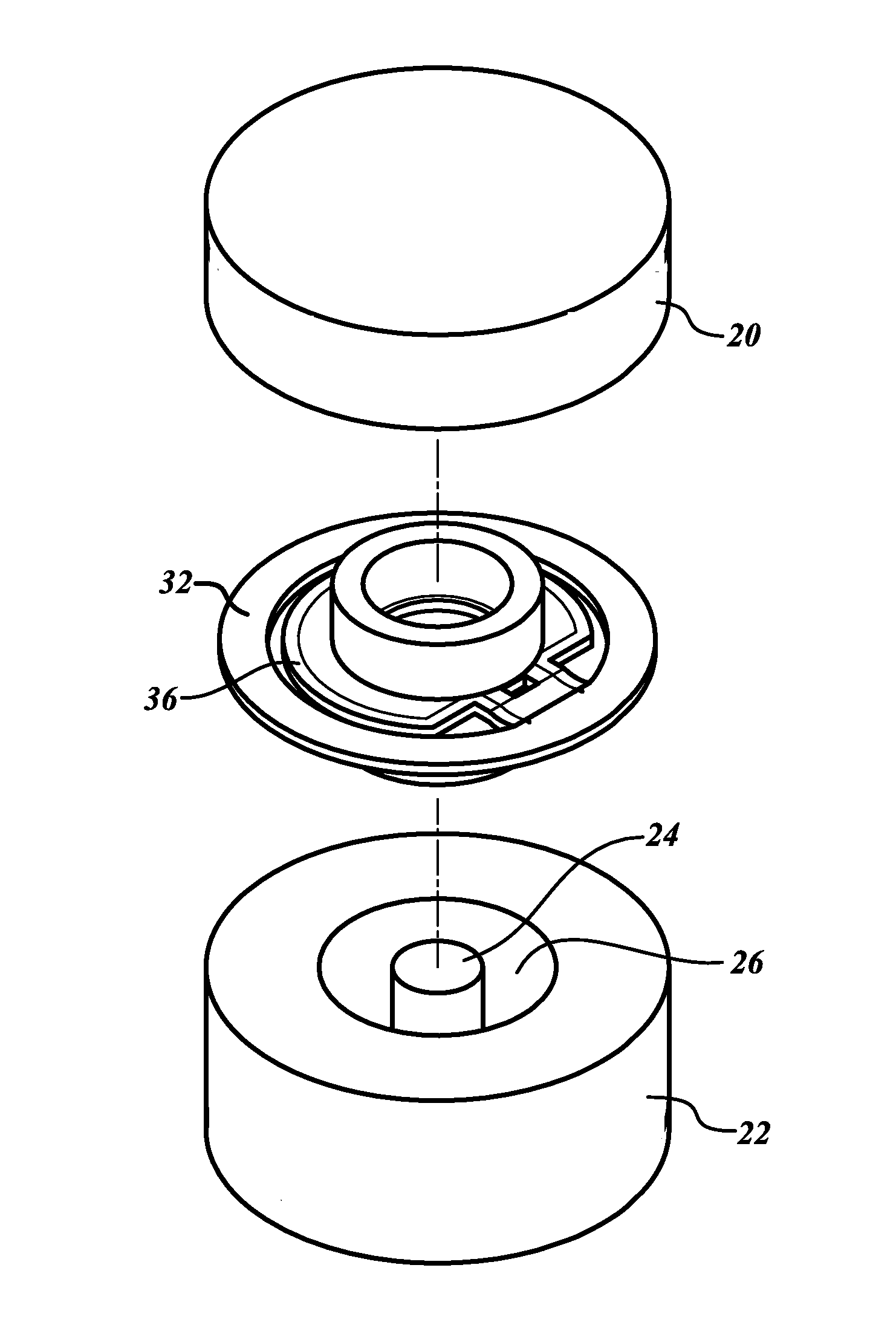
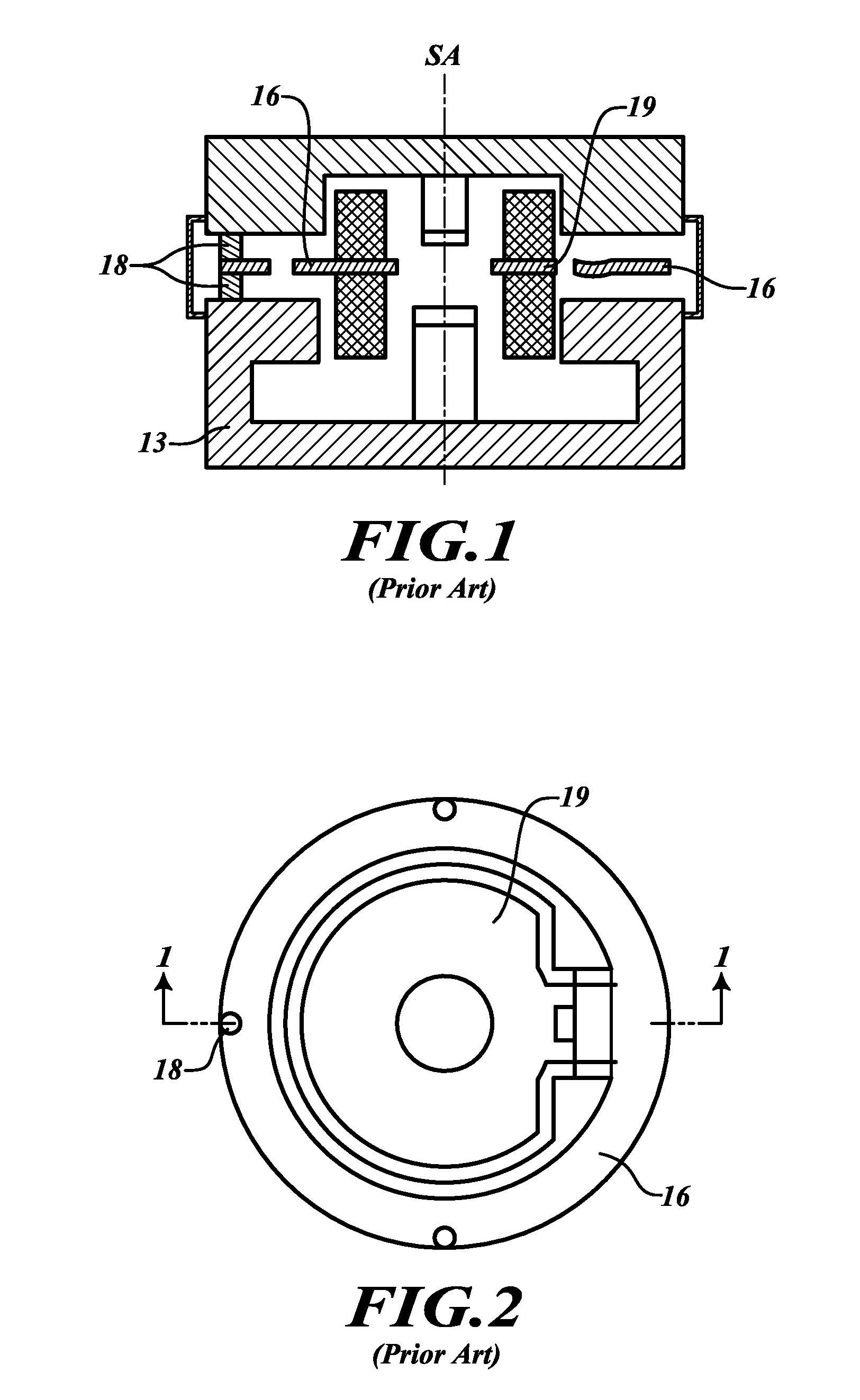
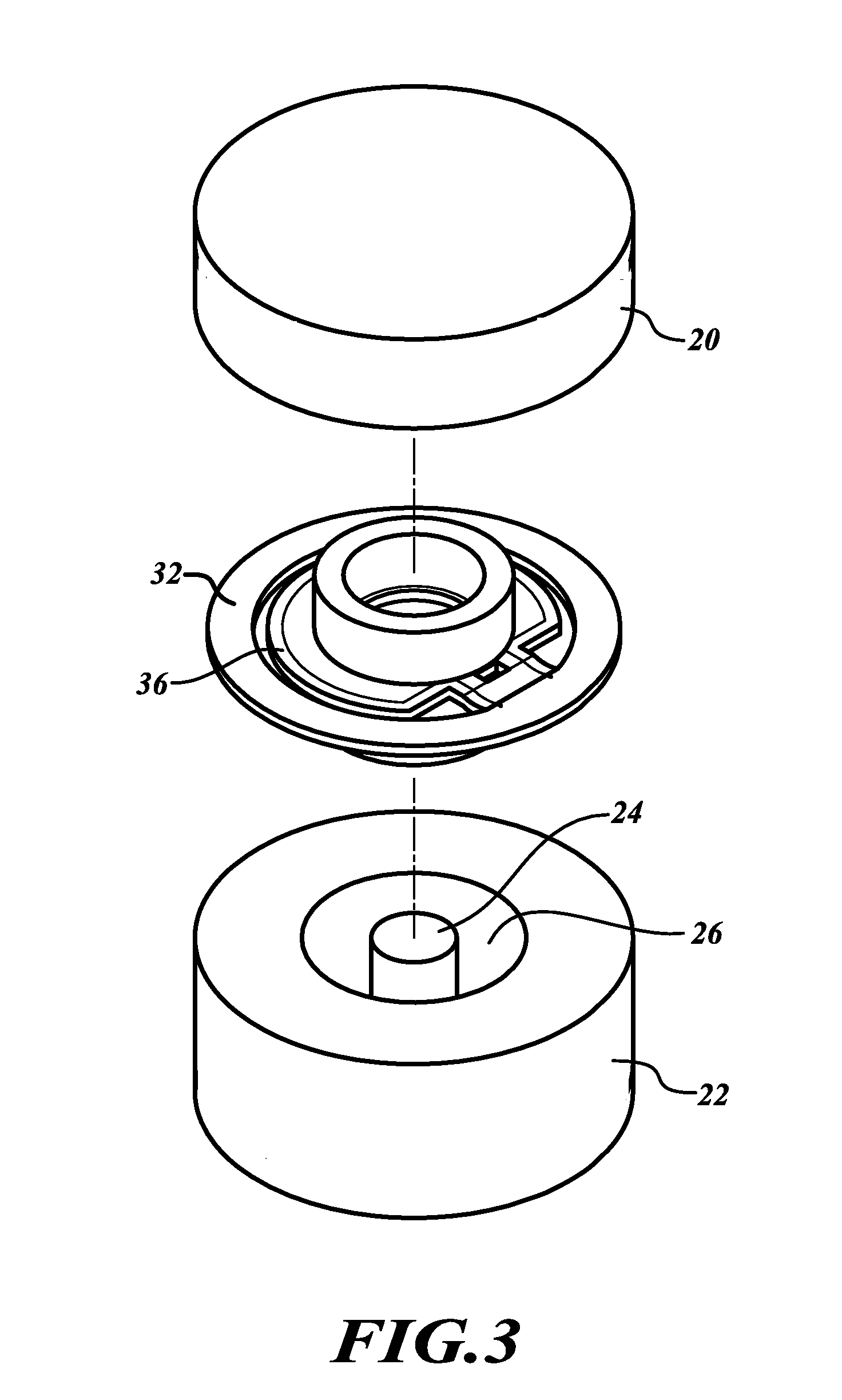
[0023]The present invention provides stress isolation / reduction features for avoiding plastic deformation, slip, or bending of a reed of an accelerometer (e.g., Q-Flex made by Honeywell, Inc.).

[0024]FIG. 3 illustrates a force rebalance accelerometer where the features of the present invention are used. This accelerometer includes an upper stator 20 and a lower stator 22. The inwardly facing surface of a least one stator includes a bore within which is positioned a permanent magnet capped by a pole piece, as illustrated by pole piece 24 within a bore 26. Also shown is reed assembly that is mounted between the upper and lower stators. The reed assembly includes a reed that includes an outer annular support ring 32 and a paddle 36 supported from the support ring by flexures. The reed is preferably fabricated from a single piece of fused silica. The support ring 32 includes three mounting locations. When the accelerometer is assembled, the mounting pads contact the upper and lower stato...


PUM


Abstract

An accelerometer device for reducing stress on the sensor resulting from temperature extremes and multiple coefficients of thermal expansion. An exemplary accelerometer device includes upper and lower stators and a reed. The reed includes a support ring and a paddle that is flexibly connected to the support ring. The support ring includes a ring section and at least two mounting devices. The mounting devices are at least partially mechanically isolated from the ring section. The ring section flexibly receives the paddle. The mounting devices include a pad area and a neck area that connect the pad area to the ring section. The neck area includes a width dimension that is narrower than a diameter dimension of the pad area.

Description

BACKGROUND OF THE INVENTION[0001]As shown in FIGS. 1 and 2, a reed is mounted to a magnetic circuit by compression. As temperature changes the much-thicker magnetic circuit component, it deforms the reed into a novel shape, which causes the paddle to deflect. Additionally, any slip of the mounting points causes error.[0002]The slip potential increases at high temperature, as the clamping force decreases and shear stress between the reed and the magnetic circuit increases.[0003]The coefficient of thermal expansion (CTE) (a) of the excitation ring 13 is higher than a of the attached reed 16. As the excitation ring 13 is also considerably stronger, it will pull mounting points 18 radially, which will also cause a compression or tensile stress as the excitation ring 13 attempts to move the mounting points 18 to a smaller or larger radius.[0004]Because the fused silica (commonly referred to as quartz) of the reed 16 is a highly elastic material, the reed 16 does not plastically deform to...

Claims


Application Information

Patent Timeline
Patent Type & Authority Applications(United States)
IPC IPC(8): G01P15/00
CPCG01P1/006G01P15/125G01P15/132
Inventor ROEHNELT, RYANJARVIS, MICHAELMAGENDANZ, GALEN
Owner HONEYWELL INT INC
Why Eureka
Try Eureka