Micro-electro-mechanical device and method for making the same

a micro-electro-mechanical and mechanical technology, applied in the field of micro-electro-mechanical devices, can solve the problems of diaphragm b>14/b> warpage and more severe warpage problems, and achieve the effect of higher density

Active Publication Date: 2014-04-24
PIXART IMAGING INC
View PDF6 Cites 28 Cited by
  • Summary
  • Abstract
  • Description
  • Claims
  • Application Information

AI Technical Summary

Problems solved by technology

However, in manufacturing the micro-electro-mechanical device 10, the manufacturing steps such as deposition, sputter, baking an annealing will cause the micro-electro-mechanical device 10 to suffer great temperature variations which easily cause the diaphragm 14 to warp due to stress release.
In addition, in order to improve sensing sensitivity, the diaphragm 14 preferably has a large area and thin thickness to enhance the signal output; however, this will cause more severe warpage problem.

Method used


Image

  • Micro-electro-mechanical device and method for making the same
  • Micro-electro-mechanical device and method for making the same
  • Micro-electro-mechanical device and method for making the same

Examples


Embodiment Construction

[0025]The drawings as referred to throughout the description of the present invention are for illustrative purpose only, but not drawn according to actual scale. The orientation wordings in the description such as: above, under, left, or right are for reference with respect to the drawings, but not for limiting the actual product made according to the present invention.

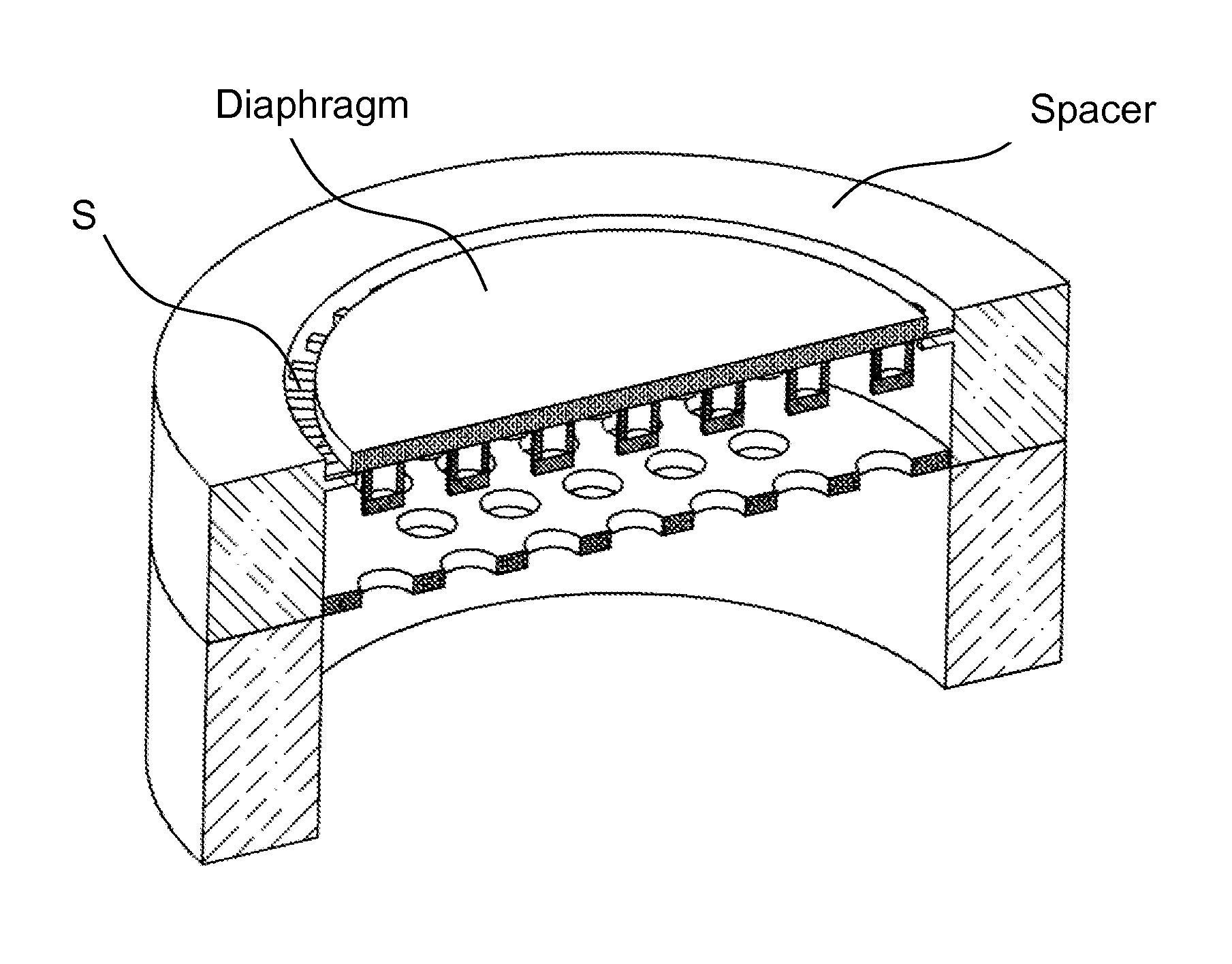
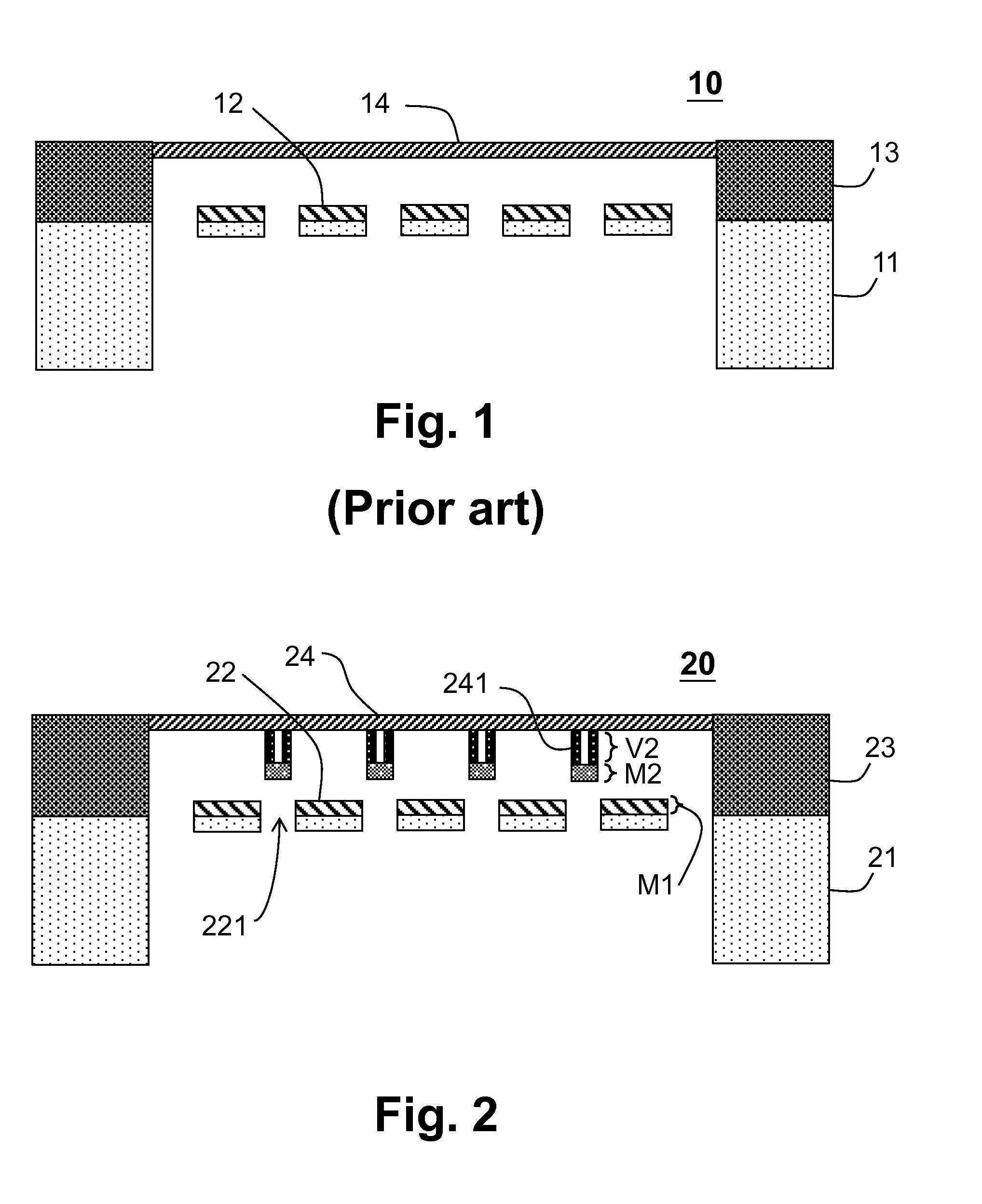
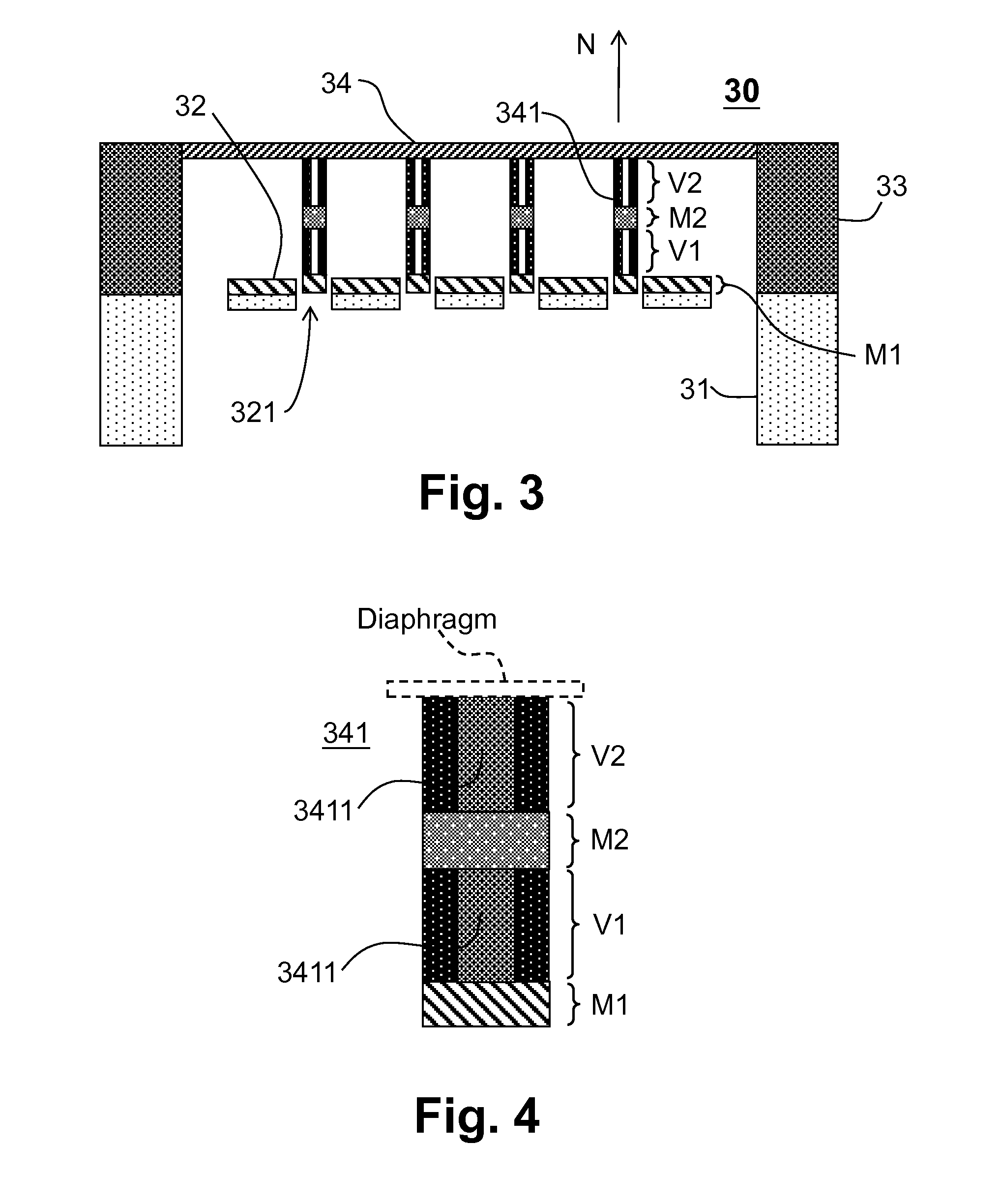
[0026]Referring to FIG. 2, a cross-section view of an embodiment of the micro-electro-mechanical device 20 according to the present invention is shown. The micro-electro-mechanical device 20 includes at least one substrate 21, an electrode 22, and a diaphragm 24, wherein the electrode 22 includes plural vent holes 221. The diaphragm 24 is disposed above and in parallel to the electrode 22, to form a capacitive sensor with the electrode 22. The diaphragm 24 includes plural ribs 241 protruding from the diaphragm 24; the ribs 241 are disposed respectively corresponding to the vent holes 221 and do not contact the electro...


PUM

PropertyMeasurementUnit
conductiveaaaaaaaaaa
densityaaaaaaaaaa
sizeaaaaaaaaaa

Abstract

The invention provides a micro-electro-mechanical device which includes a substrate, an electrode, and a diaphragm. The electrode includes plural vent holes. The diaphragm is disposed above and in parallel to the electrode, to form a capacitive sensor with the electrode. The diaphragm includes plural ribs protruding upward and / or downward from the diaphragm; the ribs are respectively disposed in correspondence to the plural vent holes and do not overlap nor contact the electrode. A method for making the micro-electro-mechanical device is also provided according to the present invention.

Description

CROSS REFERENCE[0001]The present invention claims priority to TW 101138845, filed on Oct. 22, 2012.BACKGROUND OF THE INVENTION[0002]1. Field of Invention[0003]The present invention relates to a micro-electro-mechanical device, especially a micro-electro-mechanical device which includes a plurality of ribs on (or under) a diaphragm for improving the flatness of the diaphragm, to provide a better acoustic pressure sensing capability.[0004]2. Description of Related Art[0005]Because of small size, high sensitivity, and low power consumption, micro-electro-mechanical devices are commonly used in daily life applications such as game joystick, automobile control system, and electronic products. FIG. 1 shows a cross-section view of a prior art micro-electro-mechanical device 10. The micro-electro-mechanical device 10 is for example a capacitive micro-electro-mechanical microphone which includes a substrate 11, an electrode 12, a spacer 13, and a diaphragm 14 which vibrates in response to an...

Claims


Application Information

Patent Timeline
Patent Type & Authority Applications(United States)
IPC IPC(8): G01L11/04B81C1/00
CPCB81C1/00158G01L11/04B81B3/007B81B2201/0257G01L9/0072H04R19/00H04R19/005H04R2201/003
Inventor TSAI, MING-HAN
Owner PIXART IMAGING INC
Why Eureka
Try Eureka