Modular pocket with inductive power and data

a module and pocket technology, applied in the field of module pocket systems, can solve the problems of physical weight of batteries, prone to replacing electronic device batteries, and considerable logistic burden

Active Publication Date: 2014-04-24
CYNETIC DESIGNS
View PDF3 Cites 291 Cited by
  • Summary
  • Abstract
  • Description
  • Claims
  • Application Information

AI Technical Summary

Benefits of technology

[0017]What follows is a case example of how the system would work. A soldier first of all decides where on his tactical vest he would like to mount his GPS and its pocket. The pocket is attached to the vest and connected to the power harness or bus. If he requires to use his GPS for example in an intense tactical situation, be accesses the pocket and removes the GPS without any associated disconnection of power and data cables. He uses the GPS and then simply replaces it back into his pocket without having to reconnect any power or data cables. Once the GPS is placed back into the pocket the primary circuit's proximity detection identifies the GPS, performs a handshake protocol to ensure it is a rechargeable device, the primary circuit then interrogates the devi...

Problems solved by technology

With the advent of the future soldier, this electronic burden has become an even greater contributor of the overall fighting order load and has created a considerable logistic burden with respect to the battery management of all the electronic devices the soldier is carrying.
A significant logistic issue is not only the physical weight of the batteries, but the fact that soldiers are prone to replacing their electronic device batteries whenever they think the ones installed are not sufficiently fresh.
As the devices rarely have a battery energy gauge, studies have found soldiers typically throw away up to 70% of the energy they have been carrying.
This is extremely expensive power that is thrown away from both the perspective of the soldier who carried it and never used it and the logistic replenishment support cost.
In addition soldiers do not know what batteries to take on a mission as different devices use their ow...

Method used


Image

  • Modular pocket with inductive power and data
  • Modular pocket with inductive power and data
  • Modular pocket with inductive power and data

Examples


Embodiment Construction

General Features

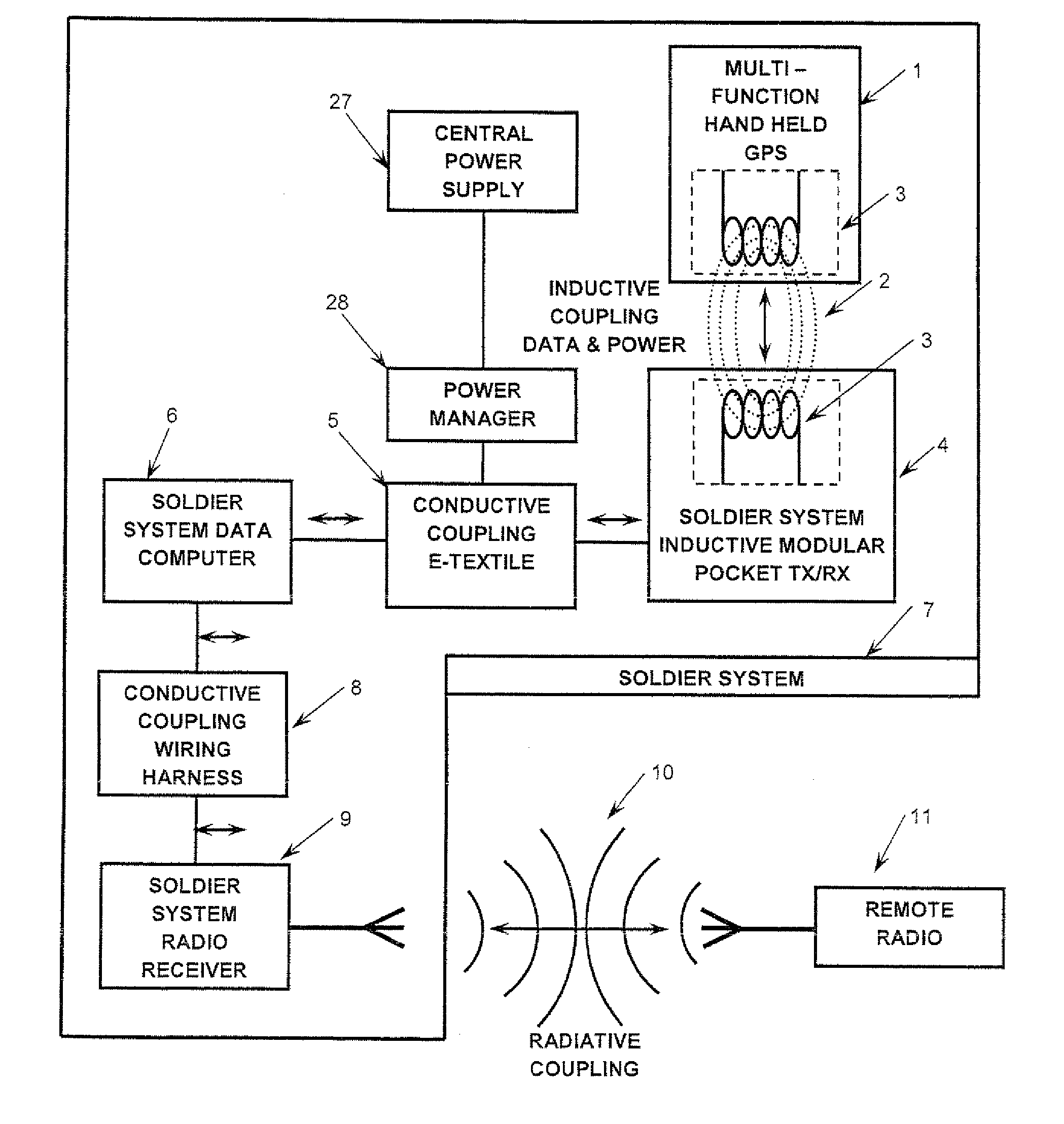
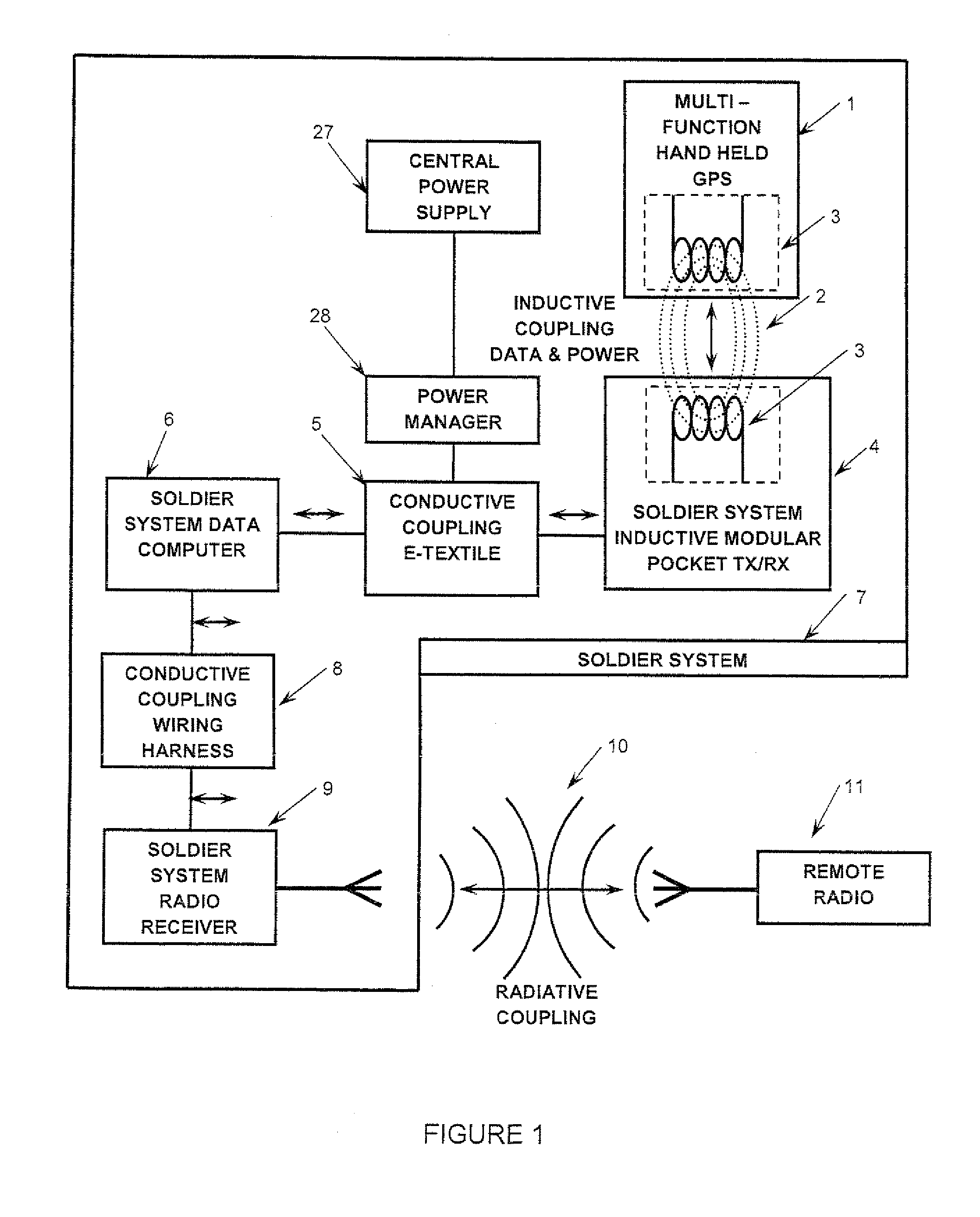
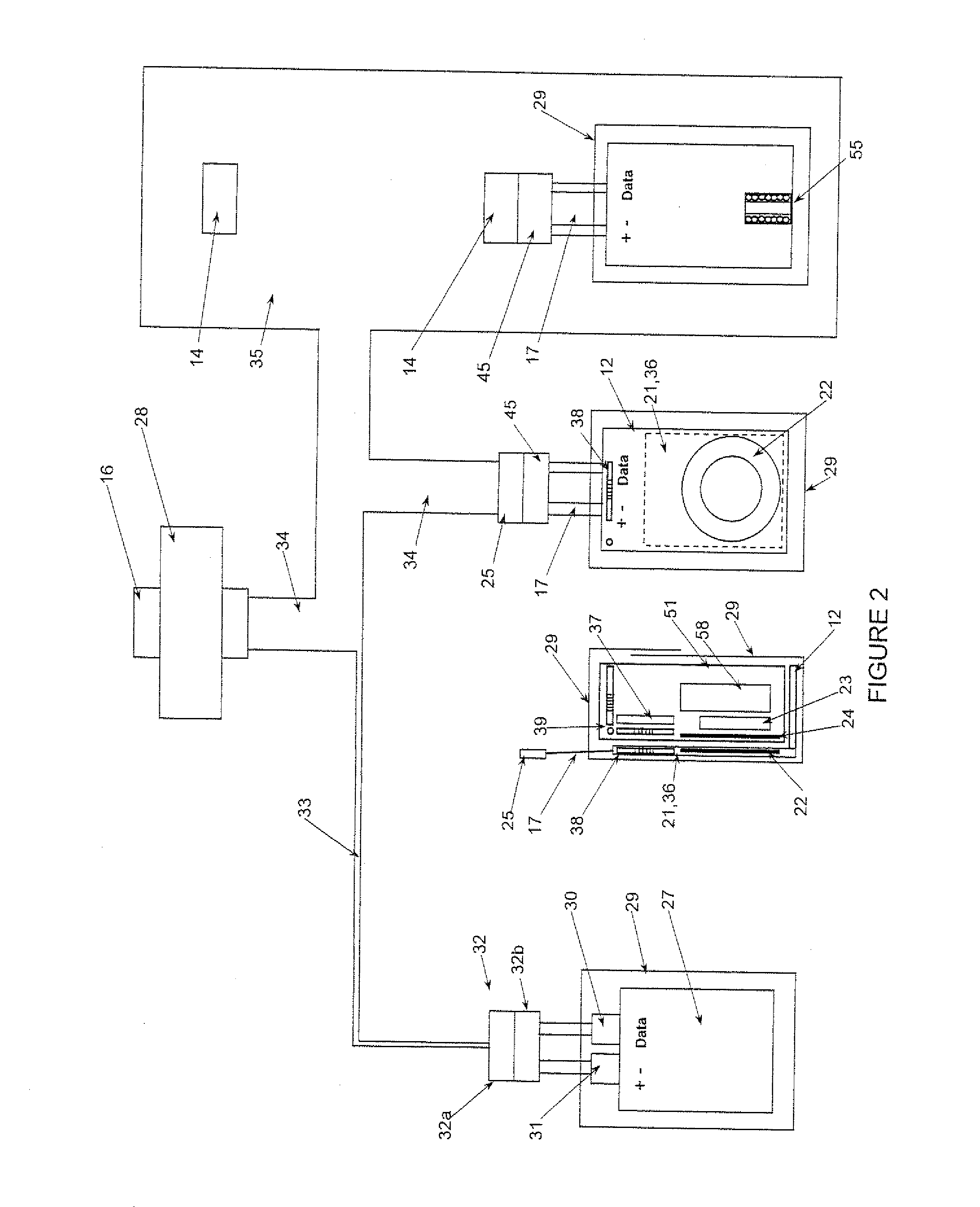
[0040]A modular pocket that allows transfer of wireless electrical power, CPM data and communication data using inductive coupling between a modular pocket and an electrical / electronic device placed within it. The modular pocket is able to be moved to different locations on the base garment and be easily and quickly reconnected with plug and play connectivity. The pocket receives and transmits its power and CPM and communications data by connecting to a conductive power and data harness integrated into the garment using conventional electro-mechanical wire, Mylar or other flexible cabling and connectors or may utilise new designs to facilitate connection to electro textiles or other power and data conductive materials.

[0041]The benefits of contactless inductive charging are many. The secondary charging circuit determines the charging voltage independent of the voltage provided to the primary side. With appropriate selection of electronic components a central supply v...


PUM


Abstract

A modular pocket system includes a modularly mountable pocket modularly mountable to a tactical garment. An insert is mounted in the pocket to align and closely inductively couple a primary inductive coil and related primary drive circuits in the insert to a secondary inductive coil and related secondary charging circuits in a portable electronic device mountable into the insert for the inductively coupled transmission of power between the coils so to transmit power to the portable device, where the device has a rechargeable energy storage component electrically connected to the secondary inductive coil and secondary charging circuits.

Description

CROSS REFERENCE TO RELATED APPLICATIONS[0001]This application is a continuation-in-part of PCT application No. PCT / CA2011 / 000128 filed Jan. 27, 2011, which claimed priority from U.S. Provisional Patent Application Ser. No. 61 / 282,350 filed Jan. 27, 2010, and which was a continuation-in-part of U.S. patent application Ser. No. 12 / 926,858 filed Dec. 14, 2010, which is a continuation of U.S. patent application Ser. No. 11 / 922,788 filed Dec. 21, 2007, now U.S. Pat. No. 7,863,859.FIELD OF THE INVENTION[0002]This invention relates to the field of devices which are inductively coupled to a charger for the charging of their batteries, fuel cells or other energy storage devices, and in particular to a modular pocket system and its pocket insert which provides for the inductively coupled transmission of power for the charging of a device held in the pocket.BACKGROUND OF THE INVENTION[0003]Soldiers have always carried a significant load when on patrol or in battle. In the recent past the load ...

Claims


Application Information

Patent Timeline
IPC IPC(8): H02J7/02
CPCH01F27/365H02J7/025H01F38/14H02J7/0044H04B5/0037H02J50/10H02J50/12H01F27/36H01F27/366H02J50/80H02J50/90
Inventor SOAR, ROGER J.
Owner CYNETIC DESIGNS
Why Eureka
Try Eureka