Crank circular sliding block mechanism and reciprocating member, cylinder block, internal combustion engine, and compressor
a circular sliding block and reciprocating mechanism technology, applied in the direction of reciprocating piston engines, machines/engines, positive displacement engines, etc., can solve the problems of large space occupation, poor balance performance large volume of crank and connecting rod mechanisms, etc., to achieve the effect of improving the space arrangement of the crank circular sliding block mechanism and reducing the space occupation
- Summary
- Abstract
- Description
- Claims
- Application Information
AI Technical Summary
Benefits of technology
Problems solved by technology
Method used
Image
Examples
first embodiment
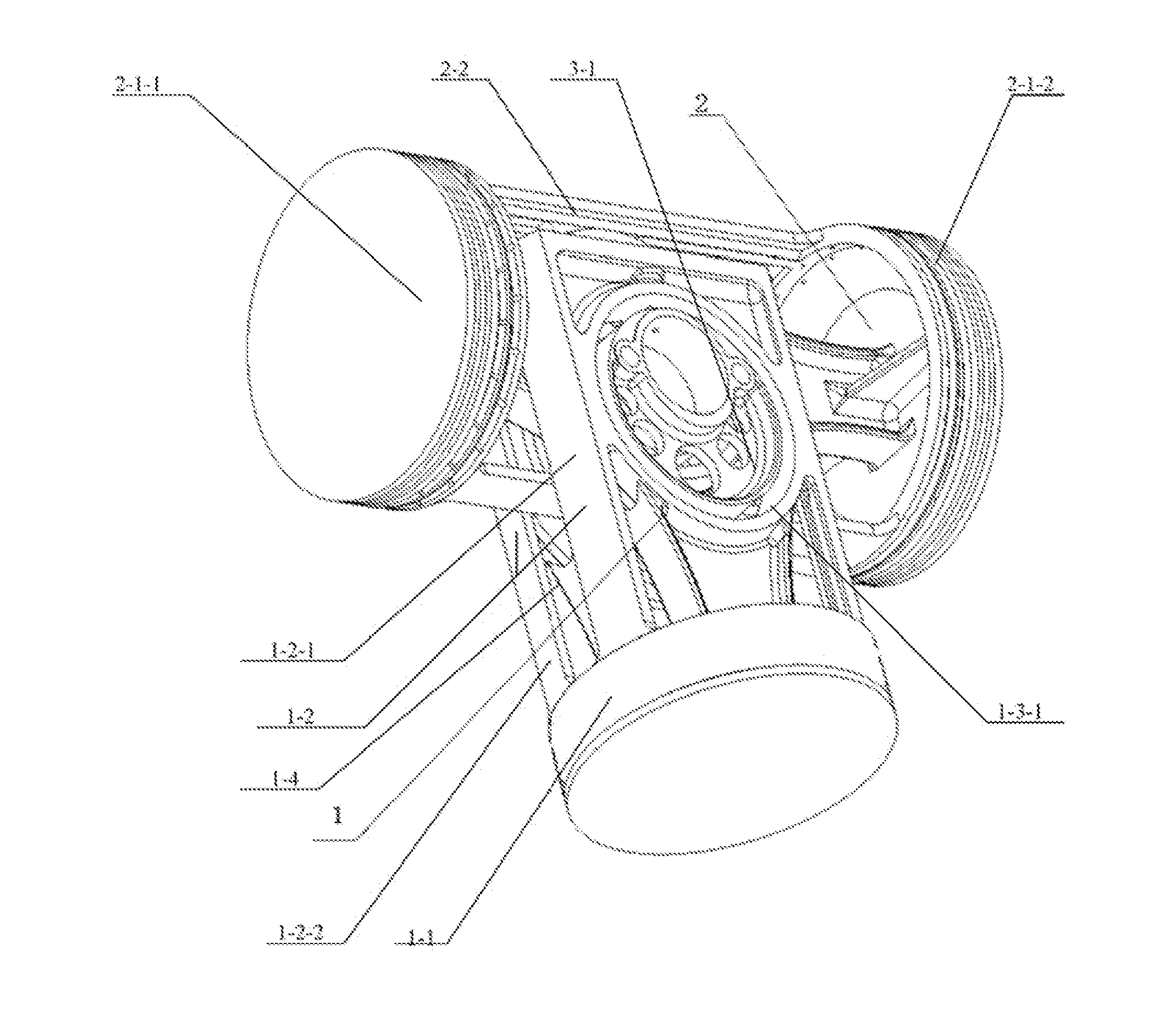
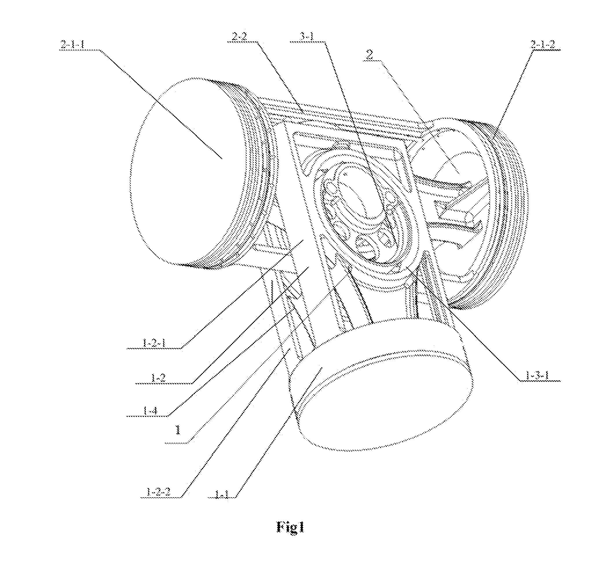
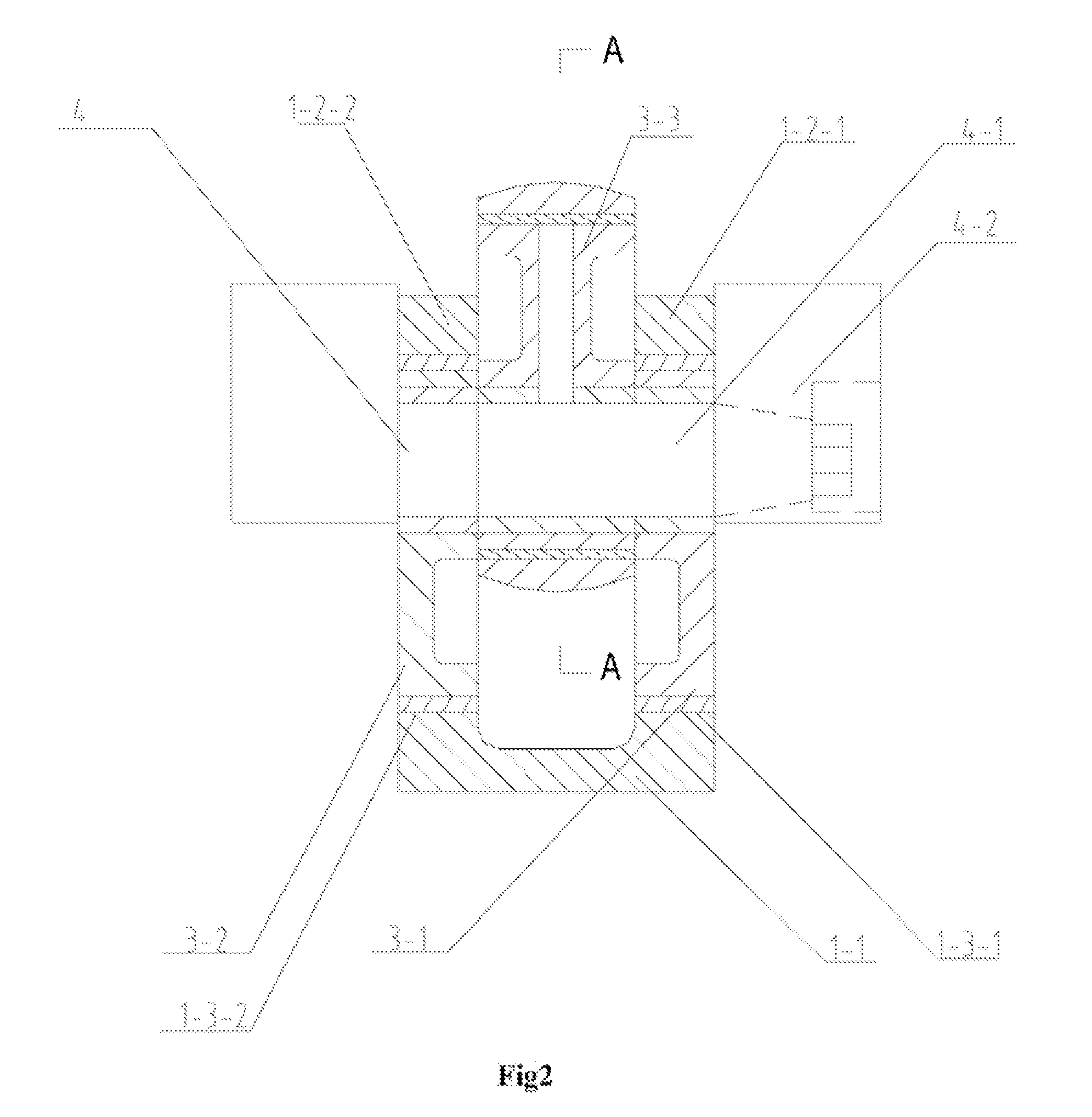
[0055]Please refer to FIG. 1, which is the schematic perspective of the I type crank circular slider mechanism proposed in the invention. In order to highlight the main features of the invention, the crankshaft of the crank circular slider mechanism is omitted in the view. Please also refer to FIG. 2, which is a plan cut view of the front face of the I type crank circular slider mechanism proposed in the embodiment. Please also refer to FIG. 3, which is a plan cut view of the I type crank circular slider mechanism proposed in the invention and is a left cut view of FIG. 2. Please also refer to FIG. 4 which is a front cut view of the dynamic balance slider 1.
[0056]As illustrated in the above figures, the I type crank circular slider mechanism comprises two reciprocating motion parts, respectively a dynamic balance slider 1 and a double action piston 2, which are placed respectively on the reciprocating motion tracks vertical to each other. The dynamic balance slider 1 moves up and do...
second embodiment
[0066]the invention provides a V type crank circular slider mechanism formed by a combination of the one single action multi-row piston and the one single action one row piston.
[0067]Please refer to FIG. 5, which is a perspective of V type crank circular slider mechanism in the second embodiment of the invention. In order to underline the features of the invention, the crankshaft is not shown in the perspective. As illustrated in FIG. 6, a partial cut view at the V type intersection (not showing the guiding part of the multi-row piston positioned in the outside) shows the second embodiment of the invention providing a V type crank circular slider mechanism. Please also refer to FIG. 7, which is a right view of A-A cut view of FIG. 6. Please also refer to FIG. 8 which is a cut front view of the multi-row piston 21.
[0068]As illustrated in the above figures, the V type crank circular slider mechanism comprises two reciprocating motion elements, respectively, a multi-row piston 21 and a...
third embodiment
[0077]the invention provides a crank circular slider mechanism for the single cylinder machine which is formed by the combination of the single action one row piston and the single crown and multi-row dynamic balance slider.
[0078]Please refer to FIG. 9, which is a perspective of the single cylinder mechanism of the crank circular slider provided by the third embodiment of the invention. In order to underline the features of the invention, the perspective does not show the crankshaft. Actually, the mechanism is required to be completely installed into the respective engine block so as to work. The mechanism may be utilized in the single cylinder internal combustion engine or the single cylinder compressor. Please refer to FIG. 10, which is a front cut view seen from one end of the crankshaft showing the single cylinder mechanism of the crank circular slider.
[0079]Please refer to FIG. 11, which is bottom cut view of the embodiment. Please refer to FIG. 12, which is a front cut view of...
PUM
 Abstract
Description
Claims
Application Information
 - R&D
- Intellectual Property
- Life Sciences
- Materials
- Tech Scout
- Unparalleled Data Quality
- Higher Quality Content
- 60% Fewer Hallucinations
Browse by: Latest US Patents, China's latest patents, Technical Efficacy Thesaurus, Application Domain, Technology Topic, Popular Technical Reports.
© 2025 PatSnap. All rights reserved.Legal|Privacy policy|Modern Slavery Act Transparency Statement|Sitemap|About US| Contact US: help@patsnap.com


