Pipe-in-pipe apparatus including an engineered pipe

a technology of engineered pipes and pipe pipes, which is applied in the direction of mechanical equipment, pipe elements, other domestic objects, etc., can solve the problems of high insulation properties that typically present low (poor) external pressure resistance, system design requirements an increase in field fabrication, and the design of a conventional pipe system. achieve the effect of reducing the risk of materials buckling, avoiding undesired movement of the flowline, and enhancing the resistance to fatigue loading

Active Publication Date: 2014-05-01
CHEVROU USA INC
View PDF6 Cites 25 Cited by
  • Summary
  • Abstract
  • Description
  • Claims
  • Application Information

AI Technical Summary

Benefits of technology

[0016]The inner engineered pipe and its end fittings will have the ability to absorb thermal expansion created by the high pressure and high temperature of the flowing production fluids. Because the inner engineered pipe has the ability to move (for example, to expand, to contract, or to deflect) inside the outer pipe, the risk of buckling the materials is reduced. The inner engineered pipe will also provide enhanced resistance to fatigue loading due to its construction (single layer or multiple layers) and associated mechanical characteristics. In addition, the inner engineered pipe will provide resistance to corrosion from transported fluid. Moreover the i

Problems solved by technology

Materials with high insulation properties typically present low (poor) external pressure resistance.
However, there are challenges associated with the design of a conventional pipe system using a PIP apparatus.
For example, this system requires an increased amount of field fabrication due to the requirement to weld and assemble two pipe strings (inner and outer pipes).
In addition, there are other challenges including, but not limited to, large thermal expansion effects and the risk of buckling the materials and connections; low cycle-high stress fatigue loading; corrosion problems wi

Method used


Image

  • Pipe-in-pipe apparatus including an engineered pipe
  • Pipe-in-pipe apparatus including an engineered pipe
  • Pipe-in-pipe apparatus including an engineered pipe

Examples


Embodiment Construction

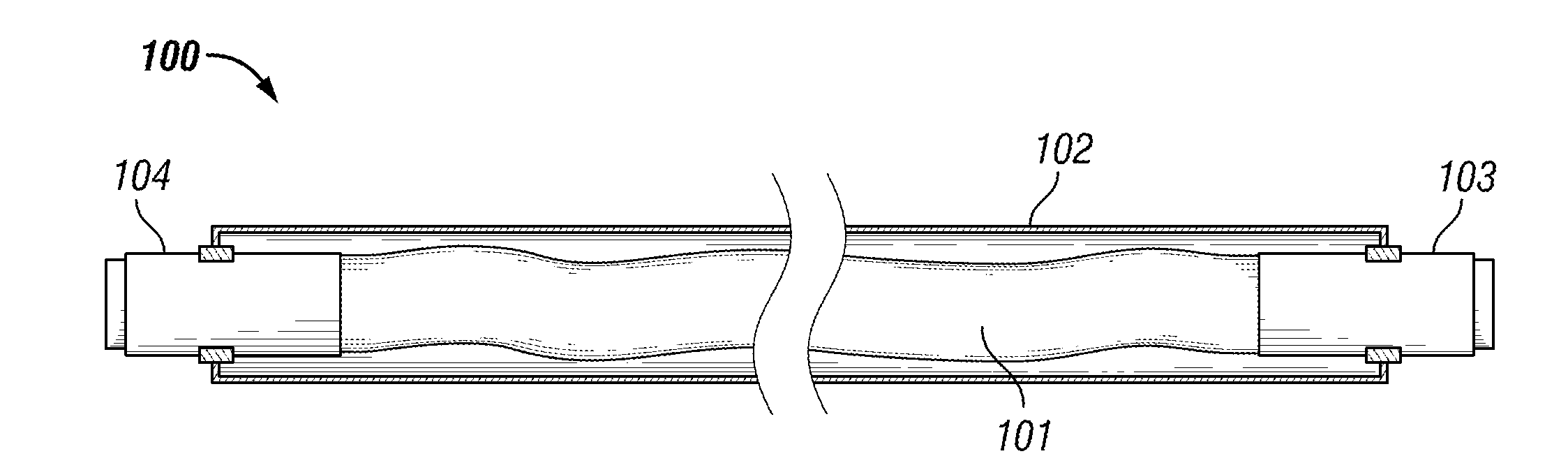
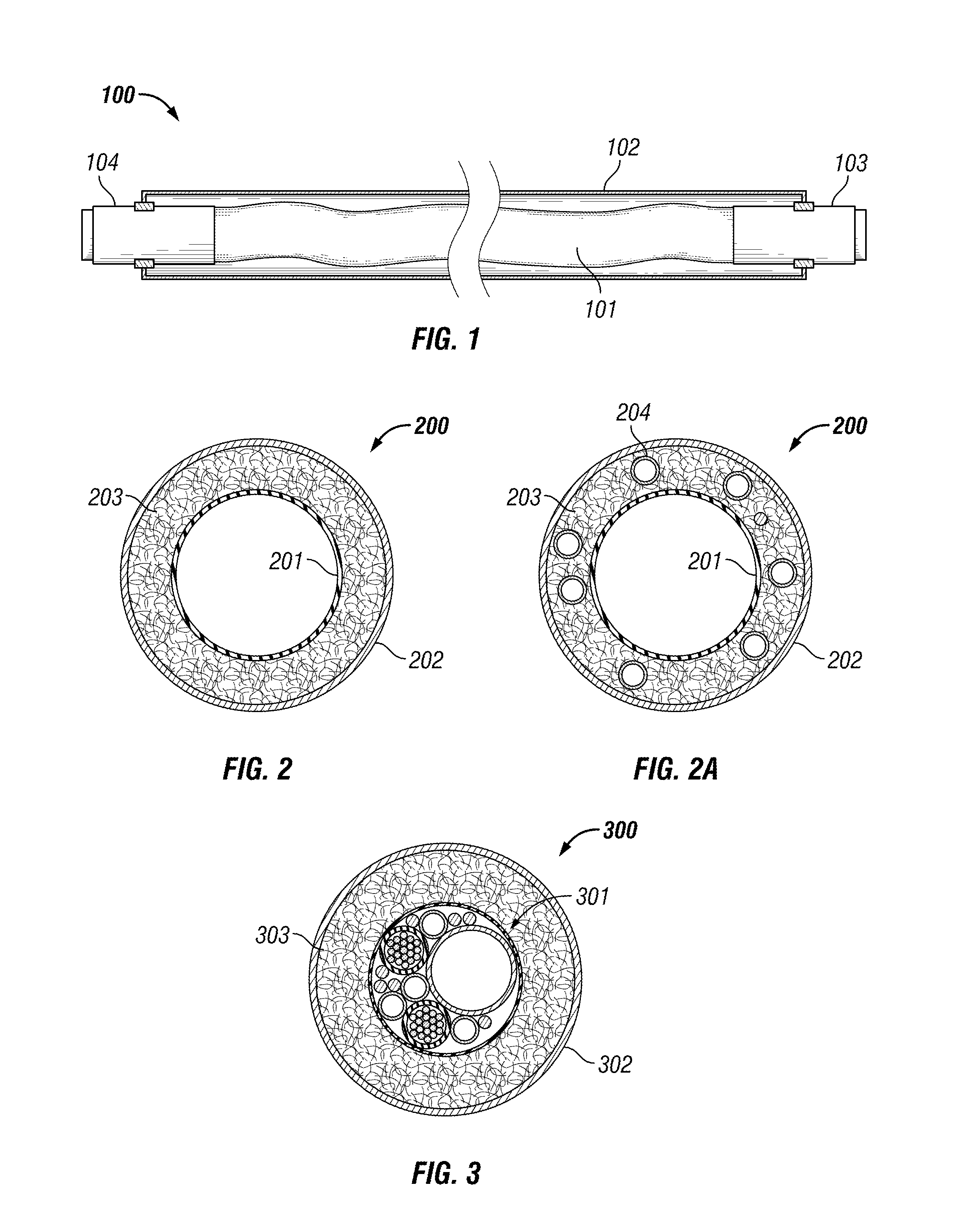
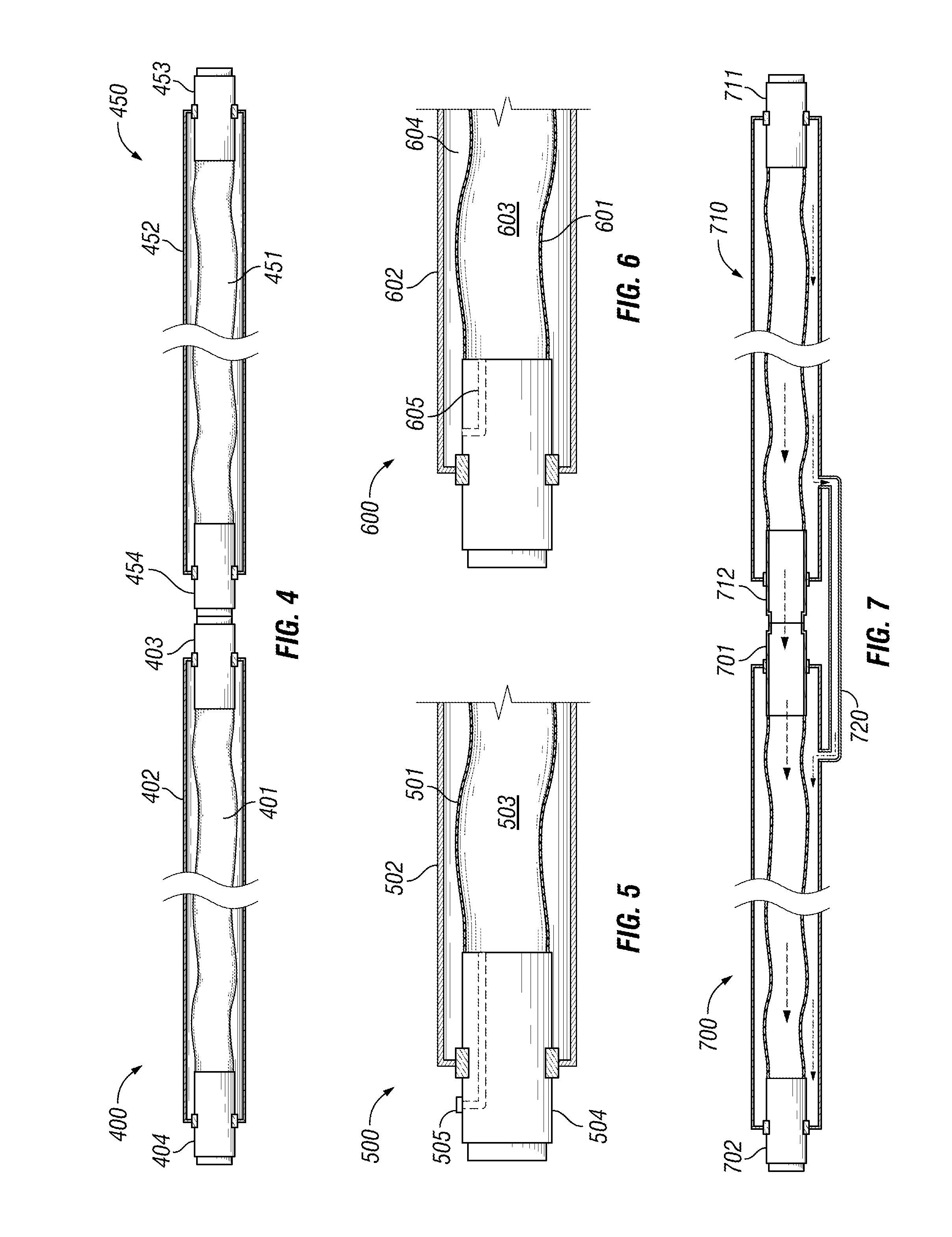
[0035]In one embodiment, an engineered pipe-in-pipe apparatus has an inner engineered pipe disposed within an outer pipe (the EIP apparatus). In one embodiment the inner engineered pipe is a flexible pipe. The outer pipe or carrier pipe may be an outer steel pipe or may be an outer engineered pipe. The outer pipe will shield the inner engineered pipe. As a result, the design of the inner engineered pipe only needs to address the functions required for the EIP apparatus.

[0036]An engineered pipe is typically terminated at each end by an end fitting which incorporates a rigid connection for mating with other connections. With the EIP apparatus, the end fitting configuration of the inner engineered pipe becomes simpler as a result of the simplified design of the inner engineered pipe. The end fitting is designed to ensure that its dimensions and profile allow easy and quick field integration of the inner engineered pipe inside the outer pipe.

[0037]FIG. 1 illustrates one embodiment of th...


PUM

PropertyMeasurementUnit
Flow rateaaaaaaaaaa
Flexibilityaaaaaaaaaa

Abstract

Disclosed is a pipe-in-pipe apparatus comprising an inner pipe disposed within an outer pipe wherein the inner pipe is an engineered pipe or umbilical. The outer pipe will shield the inner pipe. As a result, the design of the inner pipe only needs to address the functions required for the engineered pipe-in-pipe apparatus. The end fittings of the system are designed for enabling maximum operation and intervention flexibility. The engineered pipe-in-pipe apparatus will allow longer sections of the inner pipe to be used which will reduce the amount of field fabrication and streamline the installation process. The apparatus may be used for both new piping systems as well as the updating or retrofitting of an existing onshore or offshore piping system.

Description

CROSS-REFERENCE TO RELATED APPLICATIONS[0001]This application claims benefit under 35 U.S.C. §119 of U.S. Provisional Patent Application No. 61 / 720,006 with a filing date of Oct. 30, 2012. This application claims priority to and benefits from the foregoing, the disclosure of which is incorporated by reference.FIELD OF THE INVENTION[0002]This invention relates to pipe-in-pipe apparatus for conveying fluids comprising an inner pipe disposed within an outer pipe. In particular, this invention relates to such apparatus wherein the inner pipe is an engineered pipe, for example, a flexible pipe.BACKGROUND OF THE INVENTION[0003]In subsea hydrocarbon production systems, it is common practice to adopt configurations, which are effective in fulfilling several important operational objectives including, but not limited to, flow assurance, operating flexibility and reliability, while also enabling swift and safe fabrication and installation. Such systems also require means of maintaining steady...

Claims


Application Information

Patent Timeline
IPC IPC(8): F16L9/19
CPCF16L9/19F16L9/18F16L9/20F16L39/005F16L59/143Y10T29/49428
Inventor CRITSINELIS, ANTONIO C.F.KASSNER, CHRISTOPHER A.MEBARKIA, SID A.
Owner CHEVROU USA INC
Why Eureka
Try Eureka