
Pipe with rib and method for manufacturing pipe with rib

Inactive Publication Date: 2014-05-01
TOYOTA JIDOSHA KK
View PDF12 Cites 0 Cited by
  • Summary
  • Abstract
  • Description
  • Claims
  • Application Information

AI Technical Summary

Benefits of technology

The patent text describes how to make a non-linearly shaped pipe with a rib inside. The technical effect of this invention is the creation of a stronger and more reliable pipe that can withstand higher pressures and reduce the likelihood of leaks.

Problems solved by technology

It has been even more difficult to manufacture such a pipe with a rib by conventional methods.

Method used


Image

  • Pipe with rib and method for manufacturing pipe with rib
  • Pipe with rib and method for manufacturing pipe with rib
  • Pipe with rib and method for manufacturing pipe with rib

Examples


first embodiment

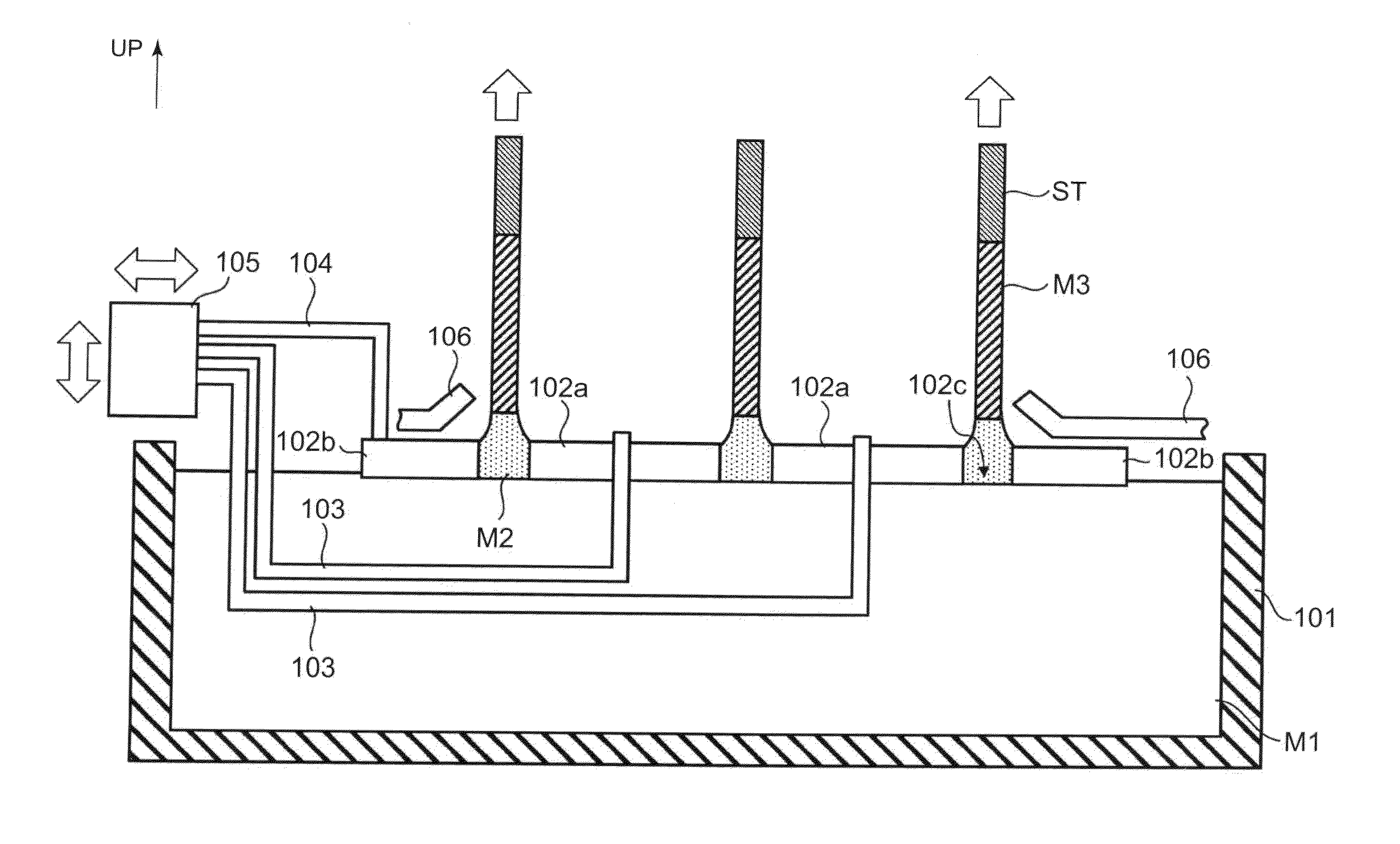
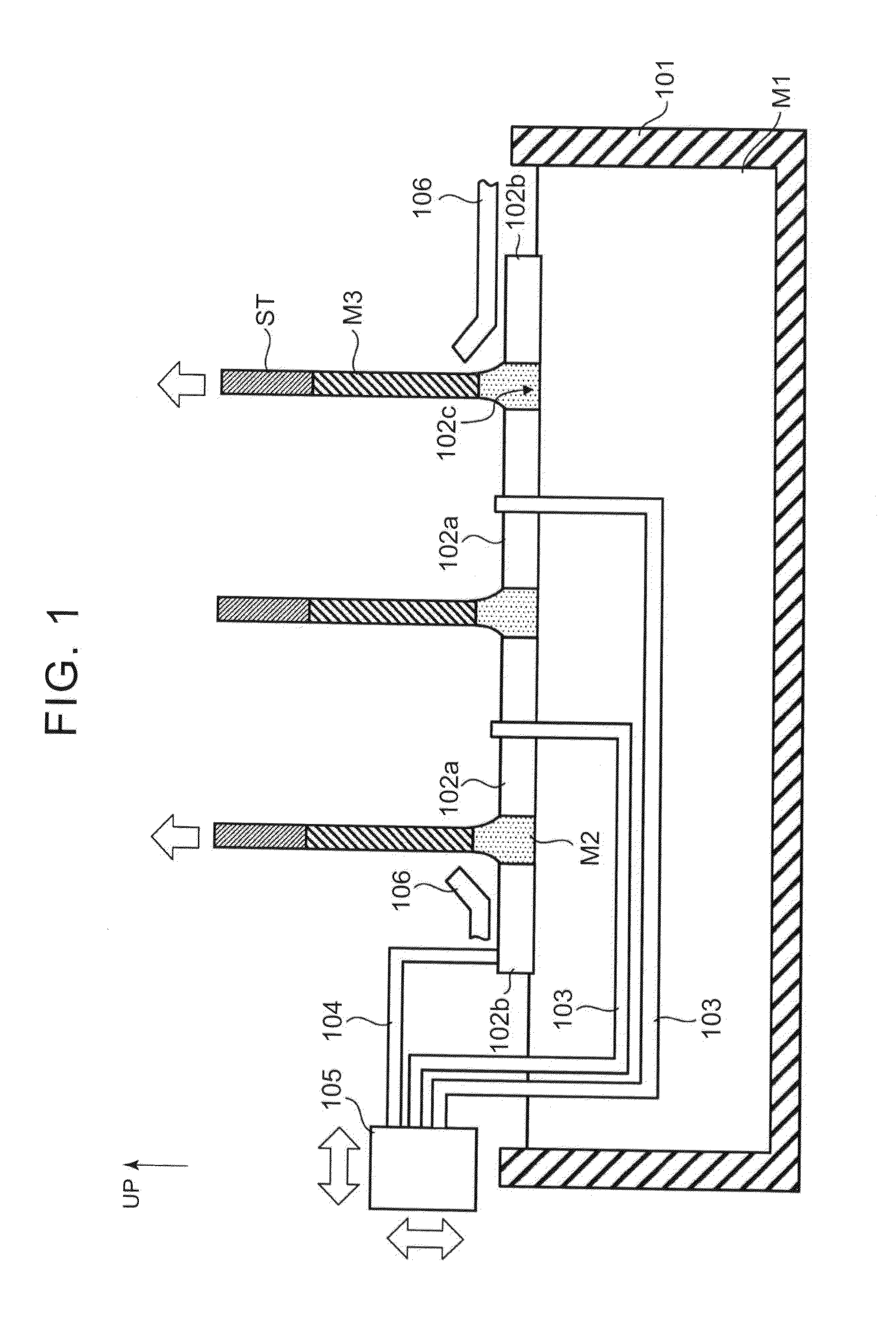
[0028]First, a free casting apparatus (an up-drawing continuous casting apparatus) according to a first embodiment will be explained with reference to FIG. 1. FIG. 1 is a sectional view of a free casting apparatus according to the first embodiment. As shown in FIG. 1, the free casting apparatus according to the first embodiment includes a molten metal holding furnace 101, inner shape defining members 102a, an outer shape defining member 102b, inner cooling gas nozzles 103, a support rod 104, an actuator 105, and outer cooling gas nozzles 106.

[0029]The molten metal holding furnace 101 holds molten metal M1 such as aluminum and an aluminum alloy, and keeps the molten metal M1 at predetermined temperature. In the example shown in FIG. 1, since the molten metal is not replenished in the molten metal holding furnace 101 during casting, a surface of the molten metal M1 (or a molten metal surface) is lowered along with a progress of casting. However, the molten metal may be replenished int...

second embodiment

[0044]A casting M3 according to a second embodiment will be explained with reference to FIG. 6A and FIG. 6B. FIG. 6A is a photograph showing external appearance of an example of the casting M3 according to the second embodiment, and FIG. 6B is an X-ray photograph of a twisted portion. The casting M3 shown in FIG. 6A includes a twisted portion 31. The casting M3 is also made of an aluminum alloy A6063 and has a section having a cross inside a square shape with a thickness of 1.5 to 2.5 mm (a gap in the molten metal passage portion 102c is 3.0 mm). FIG. 6B is an X-ray photograph of the twisted portion 31 seen from above. The twisted portion was photographed by using a digital X-ray sensor NX-06 and a portable X-ray photographic apparatus PX-20HF, made by RF Co., Ltd., under conditions with tube voltage of 74 kVp and tube current time of 25 mAs. As shown in FIG. 6B, in the twisted portion 31, a pipe portion M31 and a rib portion M32 are both twisted about a longitudinal direction of th...


PUM

PropertyMeasurementUnit
Bending strengthaaaaaaaaaa

Abstract

A pipe with a rib includes a pipe portion, and a rib portion formed inside the pipe portion. The rib portion includes a plurality of bent portions in accordance with bending of the pipe portion.

Description

[0001]The disclosure of Japanese Patent Application No. 2012-240826 filed on Oct. 31, 2012 including the specification, drawings and abstract is incorporated herein by reference in its entirety.BACKGROUND OF THE INVENTION[0002]1. Field of the Invention[0003]The invention relates to a pipe with a rib, and a method for manufacturing the pipe with a rib.[0004]2. Description of Related Art[0005]In Japanese Patent Application Publication No. 2012-61518 (JP 2012-61518 A), a free casting method is proposed as an up-drawing continuous casting method that does not require a mold. As described in JP 2012-61518 A, after a starter is immersed into a surface of molten metal (or a molten metal surface), the starter is drawn up, and then, the molten metal is also drawn out following the starter by a surface film and surface tension of the molten metal. Here, the molten metal is drawn out through a shape defining member placed near the molten metal surface, and then cooled. This way, continuous cas...

Claims


Application Information

Patent Timeline
IPC IPC(8): F16L9/00B22D25/02
CPCF16L9/003B22D25/02F16L9/006B22D11/006B22D23/00F16L9/02
Inventor FURUKAWA, YUICHIKATO, TSUKASAMORITA, KEIICHINAKAJIMA, TETSUYAYAOKAWA, JUNIWATA, YASUSHISUGIYAMA, YOSHIO
Owner TOYOTA JIDOSHA KK
Features
  • Generate Ideas
  • Intellectual Property
  • Life Sciences
  • Materials
  • Tech Scout
  • Unparalleled Data Quality
  • Higher Quality Content
  • 60% Fewer Hallucinations
Learn More