
Fill system and method including visual indicator device for empty condition

a filling system and visual indicator technology, applied in the field of adhesive pellet filling system and method, can solve the problems of slow container drop, inability to fill hands, and difficulty in gauging how much material is left in the supply container, so as to minimize the additional resistance to flow and minimize the amount of space required

Inactive Publication Date: 2014-05-01
NORDSON CORP
View PDF3 Cites 59 Cited by
  • Summary
  • Abstract
  • Description
  • Claims
  • Application Information

AI Technical Summary

Benefits of technology

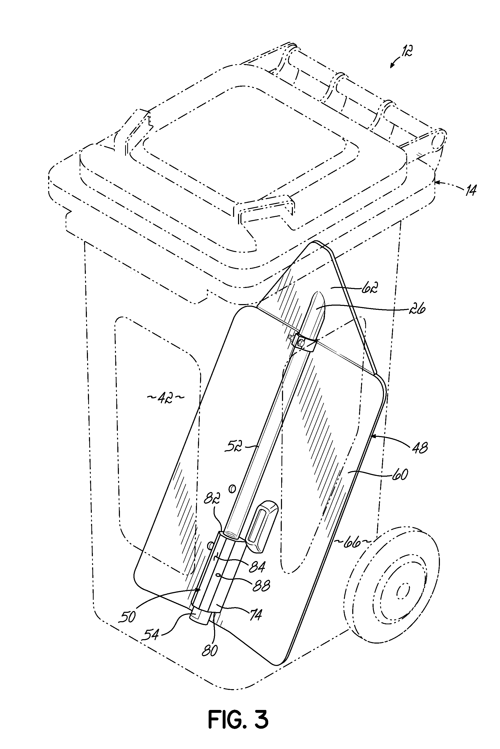
The patent describes a supply container for particulate adhesive that includes a window and a light source. The window allows for easy visual indication of the light energy emitted by the indicator device, without requiring the operator to open the lid of the supply container. The light source is mounted within the interior space of the supply container, either as additional structures or within a ramp that directs the flow of particulate adhesive towards the bottom of the interior space. The light source may also emit a flashing pattern that is detectable as a pulsing light energy when the particulate adhesive is nearly uncovered and as a flashing light energy when the light source is uncovered. The amount of fill percentage within the supply container is preferably set between 2% and 10% to provide adequate time for an operator to notice the visual indication and refill the supply container before it runs out of particulate adhesive. This invention provides a convenient and efficient way to supply particulate adhesive to the application site and minimizes operator effort.

Problems solved by technology

Some melters are designed in such a manner that hand filling is not possible.
In addition, the level of pellets within the supply container drops at a slow pace during normal operation, so it can be difficult to gauge how much material is left in the supply container, and when the supply container will need to be refilled.
These problems of detecting the level of pellets within the supply container are particularly exacerbated when the pellet level is only checked by an operator opening a lid at the top of the supply container and looking down into the supply container.
This refilling process and the resulting restart process for the dispensing system can cause significant downtime if the empty condition of the supply container is not anticipated and addressed in advance of the supply container reaching the empty condition.

Method used


Image

  • Fill system and method including visual indicator device for empty condition
  • Fill system and method including visual indicator device for empty condition
  • Fill system and method including visual indicator device for empty condition

Examples


Embodiment Construction

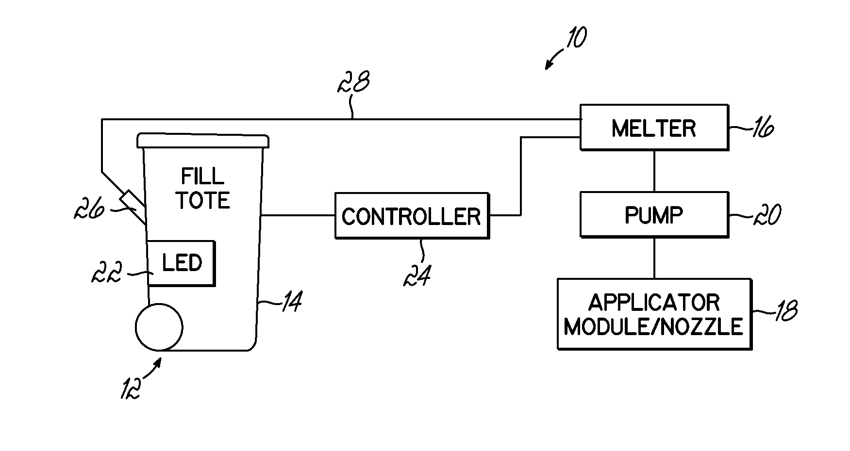
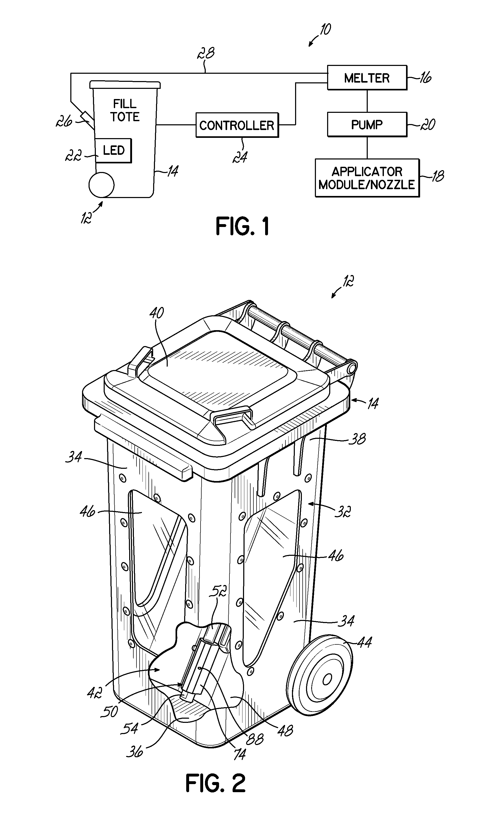
[0026]Referring to FIG. 1, an adhesive dispensing system 10 in accordance with one embodiment of the invention includes a fill system 12 that is configured to provide a visual indication when the particulate adhesive within a supply container 14 is approaching an empty condition. More specifically, the fill system 12 is used to provide adhesive pellets to a melter 16 of the adhesive dispensing system 10, and the melter 16 feeds liquefied molten adhesive to an applicator module or nozzle 18 using a liquid pump 20. In this regard, the fill system 12 is operated to continually replenish the supply of adhesive within the melter 16 as the pump 18 removes molten adhesive for dispensing at the applicator module or nozzle 18. The adhesive material may define any form or shape that is convenient for delivering by the fill system 12 and for melting by the adhesive melter 16; however, “pellets” have been chosen for illustrative purposes in the illustrated embodiment. It will be understood that...


PUM

PropertyMeasurementUnit
Fractionaaaaaaaaaa
Fractionaaaaaaaaaa
Temperatureaaaaaaaaaa

Abstract

A fill system is configured to supply particulate adhesive such as pellets to an adhesive dispensing system and is configured to provide a visual indication when a supply container approaches an empty condition. The fill system includes the supply container, which has an interior space for holding pellets, and an indicator device that emits a visual indication by actuating a light source communicating with the interior space. As a result, when the level of pellets within the interior space drops to a threshold approaching the empty condition, the light energy emitted by the indicator device is visible outside the supply container. The fill system may then be refilled before the completely empty condition is reached.

Description

FIELD OF THE INVENTION[0001]The present invention generally relates to particulate material filling systems and more particularly, to an adhesive pellet filling system and method used with adhesive dispensing systems.BACKGROUND[0002]A conventional dispensing system for supplying heated adhesive (i.e., a hot-melt adhesive dispensing system) generally includes a melter having an inlet for receiving adhesive materials in solid or liquid form, a heater grid or cartridge for heating the adhesive materials, an outlet for receiving the heated adhesive, and a pump in communication with the outlet for driving and controlling the dispensation of the heated adhesive through the outlet. One or more hoses may also be connected to the outlet to direct the dispensation of heated adhesive to adhesive dispensing guns or modules located downstream from the melter. Furthermore, conventional dispensing systems generally include a controller (e.g., a processor and a memory) and input controls electrical...

Claims


Application Information

Patent Timeline
IPC IPC(8): B65B1/48
CPCB05C11/101B05C11/1042
Inventor CLARK, JUSTIN A.ESTELLE, PETER W.
Owner NORDSON CORP
Learn More