Bus bar assembly and method of manufacturing the same

a technology of bus bars and assembly methods, applied in the direction of laminated bus bars, conductors, single bars/rods/wires/strips conductors, etc., can solve the problems the inductance may not be sufficiently reduced, and the problem of increasing the size of the overall bus bar assembly, so as to achieve accurate positioning, reduce the effect of inductance and facilitate the positioning of the bus bar

Active Publication Date: 2014-05-01
DENSO CORP
View PDF10 Cites 21 Cited by
  • Summary
  • Abstract
  • Description
  • Claims
  • Application Information

AI Technical Summary

Benefits of technology

[0031]In this instance, the first end in the width direction Y of each bus bar can be supported in the width direction Y and the thickness direction Z by the concavity of the jig provided in the first die. In other words, the bus bars can be accurately positioned by only the first die of the dies. As a result, in the bus bar placement process, positioning of the bus bars is facilitated. In addition, when the bus bar is placed in the concavity of the jig in the first die first, a subsequent operation of disposing the second die on the first die can be facilitated. The first die and the jig provided in the first die may be configured separately or as a single body.
[0032]As described above, according to the present application, a bus bar assembly in which inductance can be sufficiently reduced and a method for manufacturing the bus bar assembly can be provided.

Problems solved by technology

As a result, inductance may not be sufficiently reduced.
This problem becomes more significant as the number of bus bars increases.
When the size of the bus bars is increased, a problem occurs in that the overall bus bar assembly increases in size.

Method used


Image

  • Bus bar assembly and method of manufacturing the same
  • Bus bar assembly and method of manufacturing the same
  • Bus bar assembly and method of manufacturing the same

Examples


first embodiment

[0060]First embodiment of the present invention will hereinafter be described with reference to FIG. 1 to FIG. 18.

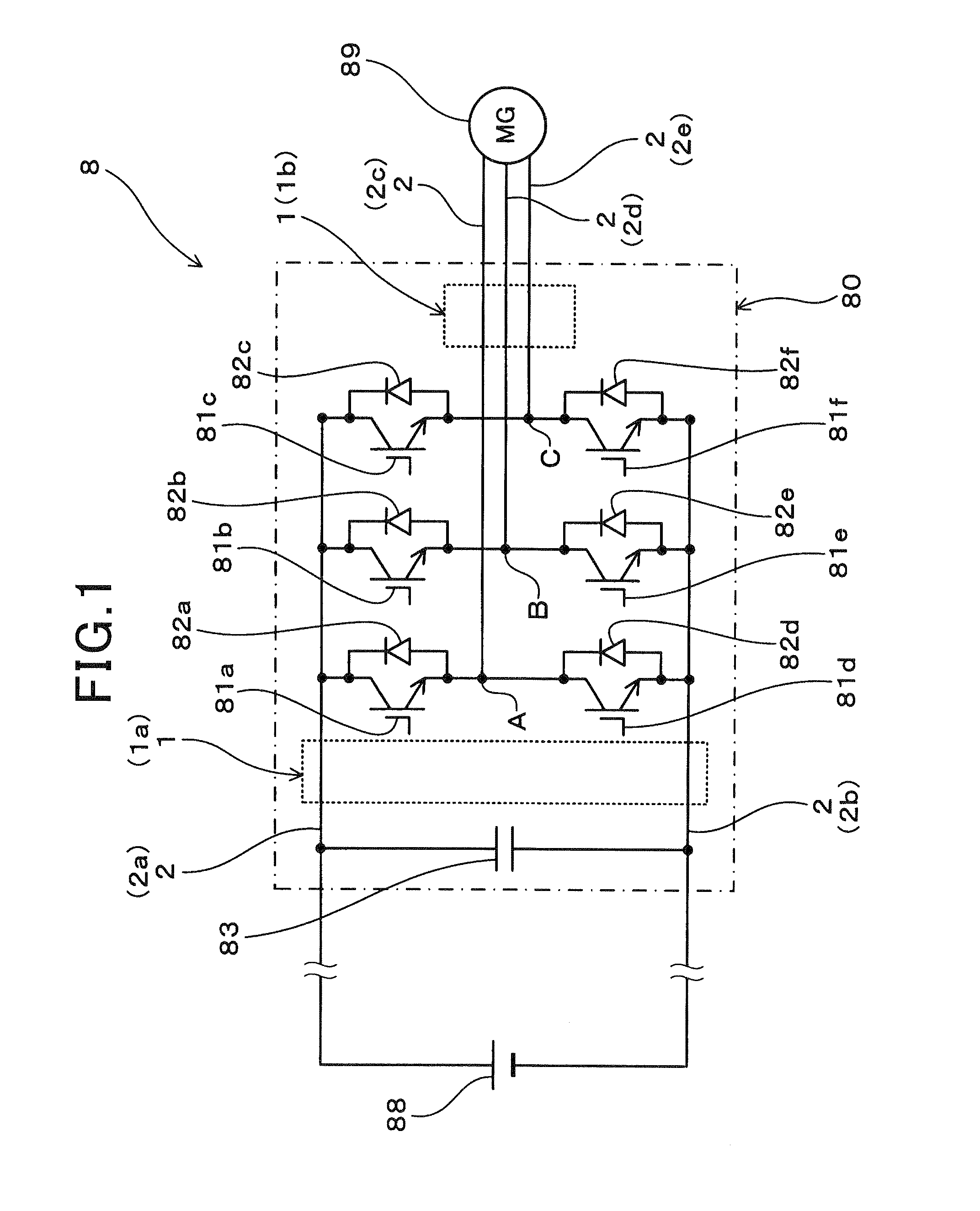
[0061]FIG. 1 illustrates a circuit diagram of a power conversion device according to a first embodiment. As shown in FIG. 1, a bus bar assembly 1 (1a) according to the first embodiment is applied to a power conversion device 8 that controls a three-phase alternating-current motor 89 for cruising that is mounted in a vehicle. The power conversion device 8 includes an inverter 80 that drives the three-phase alternating-current motor 89. Inverter insulated-gate bipolar transistors (IGBTs) 81a to 81f, freewheeling diodes 82a to 82f, and a capacitor 83 are disposed in the inverter 80.

[0062]As shown in FIG. 1, the inverter IGBTs 81a to 81f are switching elements that are repeatedly turned ON and OFF accordingly to convert direct-current voltage inputted into the inverter 80 to alternating-current voltage. The collectors of the inverter IGBTs 81a to 81c are connected to the pos...

second embodiment

[0088]Second embodiment of the present invention will hereinafter be described with reference to FIG. 19 to FIG. 25.

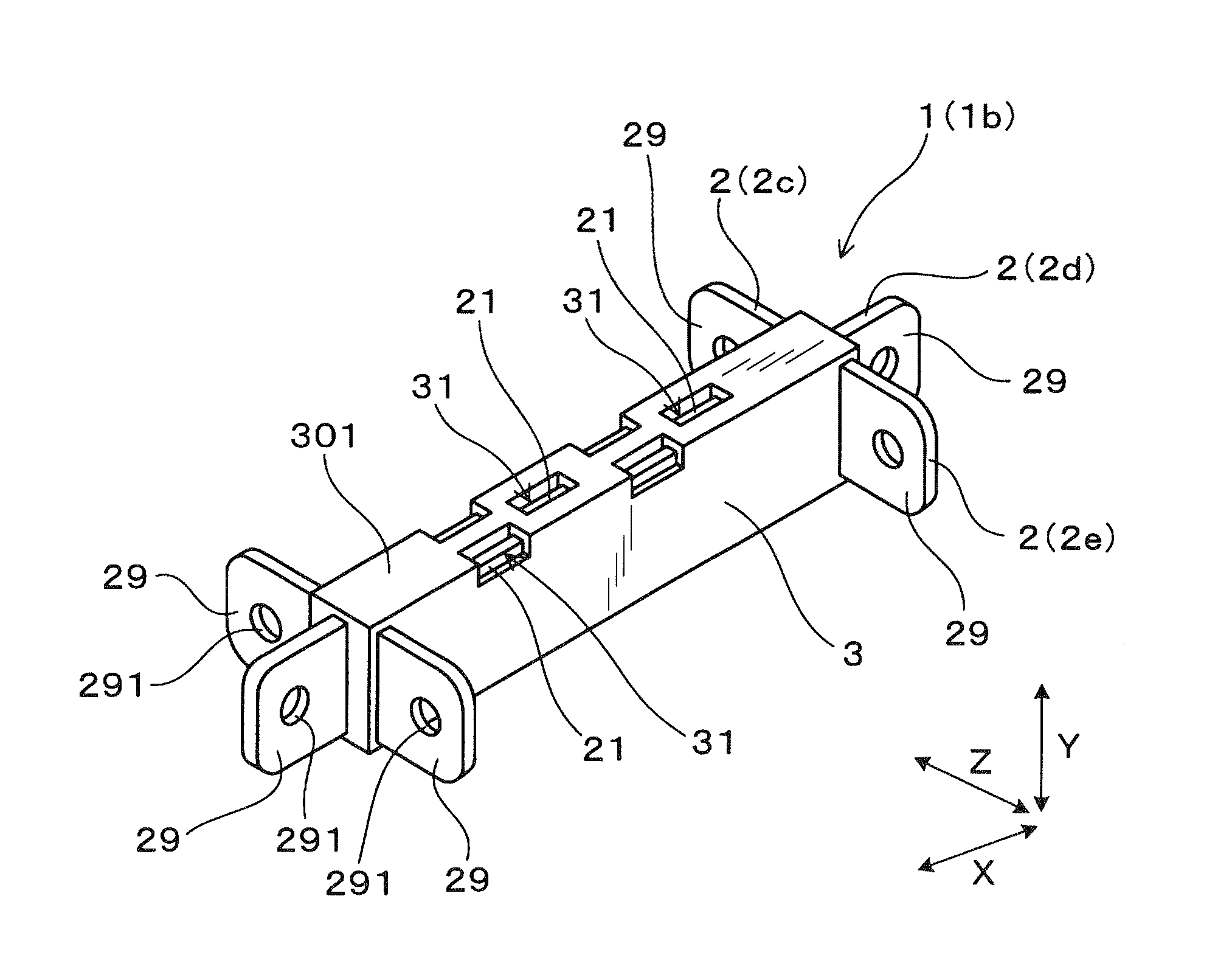
[0089]A second embodiment is an example that is a bus bar assembly 1b shown in FIG. 1, or in other words, an instance in which the number of bus bars 2 is three. As shown in FIG. 1, in a manner similar to that according to the first embodiment, the bus bar assembly 1 (1b) according to the second embodiment is applied to the power conversion device 8 that controls the three-phase alternating-current motor 89 for cruising that is mounted in a vehicle. The bus bar assembly 1 (1b) is disposed within the inverter 80 in a state in which the U-phase bus bar 2c, the V-phase bus bar 2d, and the W-phase bus bar 2e are molded into a single body by an insulating resin.

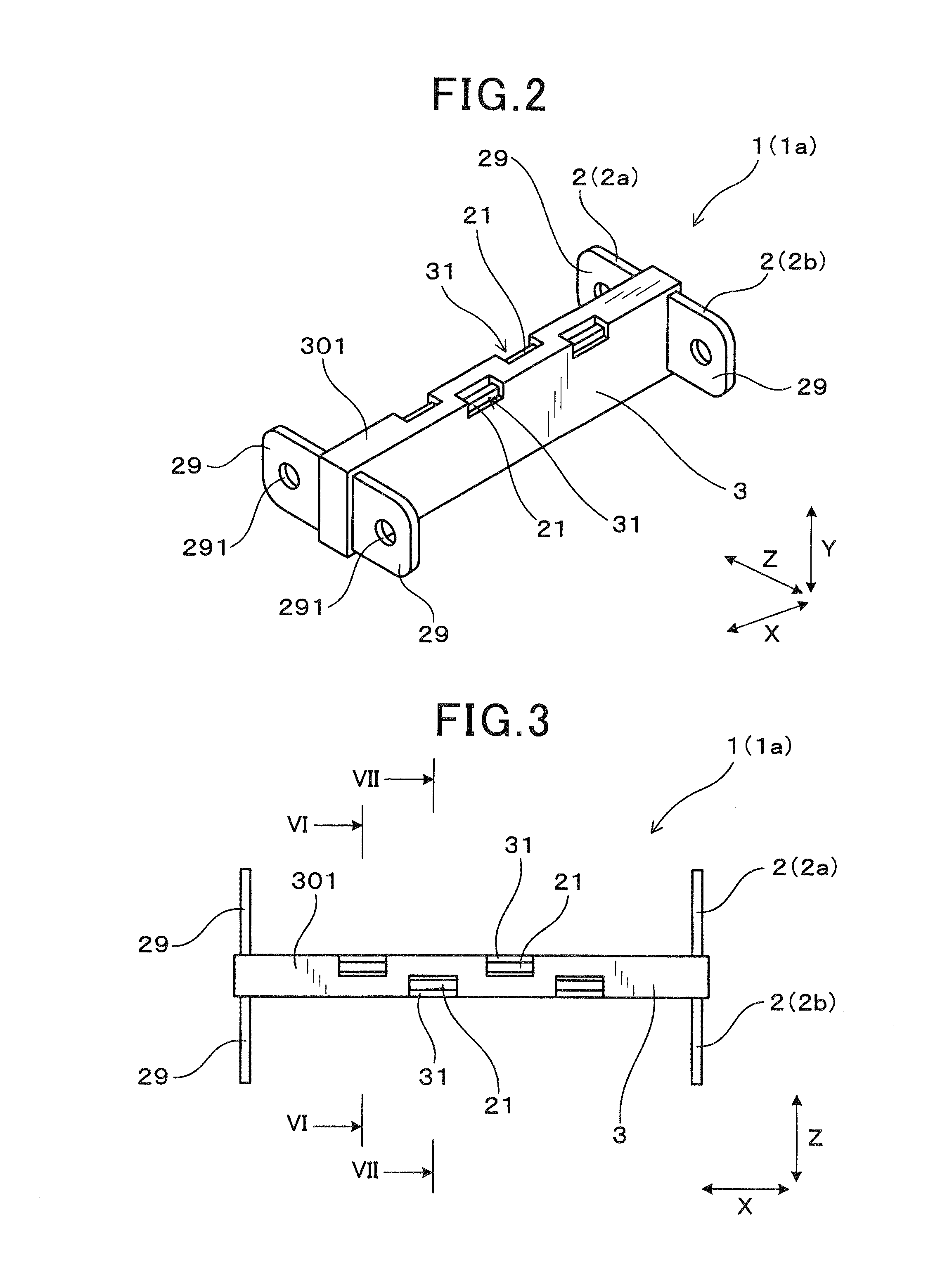
[0090]Specifically, as shown in FIG. 19 to FIG. 22, the bus bar assembly 1 (1b) includes three bus bars 2. Here, FIG. 19 illustrates a perspective view of the bus bar assembly according to the second embodiment. FIG....


PUM

PropertyMeasurementUnit
conductiveaaaaaaaaaa
thicknessaaaaaaaaaa
widthaaaaaaaaaa

Abstract

A bus bar assembly comprises a plurality of conductive plate-shaped bus bars and a resin mold section in which a plurality of conductive plate-shaped bus bars are partially embedded. In a method for manufacturing the bus bar assembly, firstly a plurality of conductive plate-shaped bus bars are disposed within a cavity formed by a die such as to be stacked in a thickness direction Z with a predetermined amount of space therebetween. Second, a first end and a second end of each bus bar are respectively supported by jigs in the width direction Y. Next, the cavity in the die is filled with the insulating resin and the plurality of bus bars are molded into a single body. After that, jigs are removed from the bus bars and jig placement portions are formed in the resin mold section.

Description

CROSS-REFERENCE TO RELATED APPLICATION[0001]This application is based on and claims the benefit of priority from earlier Japanese Patent Application No. 2012-240159 filed Oct. 31, 2012, the description of which is incorporated herein by reference.BACKGROUND OF THE INVENTION[0002]1. Field of the Invention[0003]The present invention relates to a bus bar assembly formed by a plurality of bus bars being molded by an insulating resin, and a method for manufacturing the bus bar assembly.[0004]2. Description of the Related Art[0005]A power conversion device that converts direct-current power from a battery to alternating-current power is used in hybrid vehicles and electric cars. Electrical components, such as switching elements, capacitors, and reactors, are included within the power conversion device. A bus bar composed of a conductor is used to connect the terminals of these electric components.[0006]JP-A-2011-35277 discloses a bus bar assembly that includes a plurality of bus bars and ...

Claims


Application Information

Patent Timeline
Patent Type & Authority Applications(United States)
IPC IPC(8): H02G5/00B29C70/84
CPCH02G5/005B29C70/84H02M7/003
Inventor HATORI, KOUJI
Owner DENSO CORP
Why Eureka
Try Eureka