Non-Contact Charging Apparatus for Mobile Body and Non-Contact Charging Method for Mobile Body

a technology of non-contact charging and mobile body, which is applied in the direction of charging stations, electric vehicle charging technology, transportation and packaging, etc., can solve the problems of difficult to find an area of sufficient size, difficult to charge a secondary battery mounted in the mobile body in a short period of time, and inability to enhance power transmission efficiency, etc., to achieve the effect of enhancing power transmission efficiency

Inactive Publication Date: 2014-05-01
HITACHI LTD
View PDF1 Cites 18 Cited by
  • Summary
  • Abstract
  • Description
  • Claims
  • Application Information

AI Technical Summary

Benefits of technology

[0010]According to the present invention, a plurality of receiving parts are prepared and distributively arranged in a mobile body, making it possible for electric power to be transmitted in a non-contact manner to

Problems solved by technology

A mobile body, such as an electric car, has size and shape constraints in terms of places where a power-receiving device can be installed, and it is therefore difficult to charge a secondary battery mounted in the mobile body in a short period of time.
F

Method used


Image

  • Non-Contact Charging Apparatus for Mobile Body and Non-Contact Charging Method for Mobile Body
  • Non-Contact Charging Apparatus for Mobile Body and Non-Contact Charging Method for Mobile Body
  • Non-Contact Charging Apparatus for Mobile Body and Non-Contact Charging Method for Mobile Body

Examples


embodiment 1

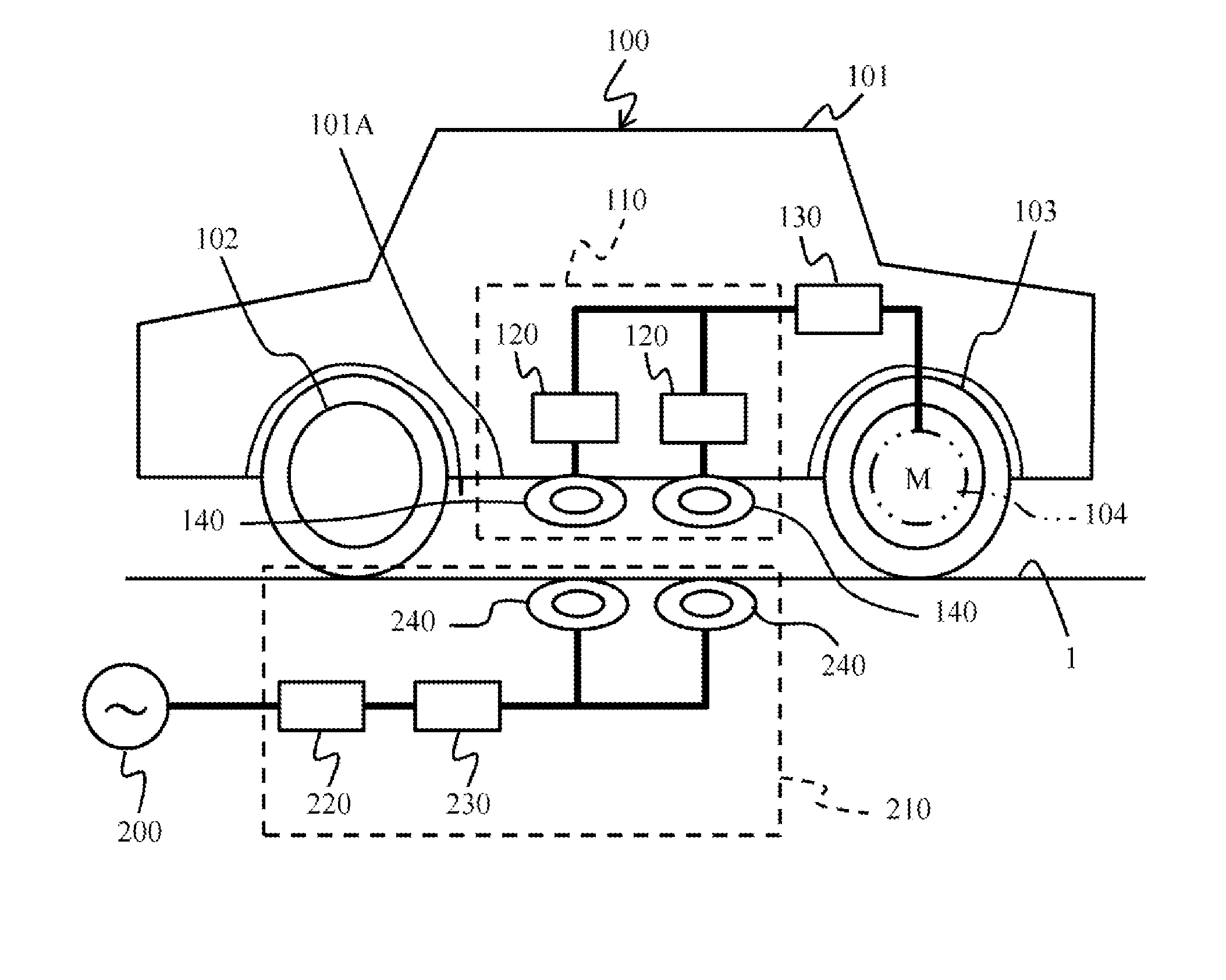
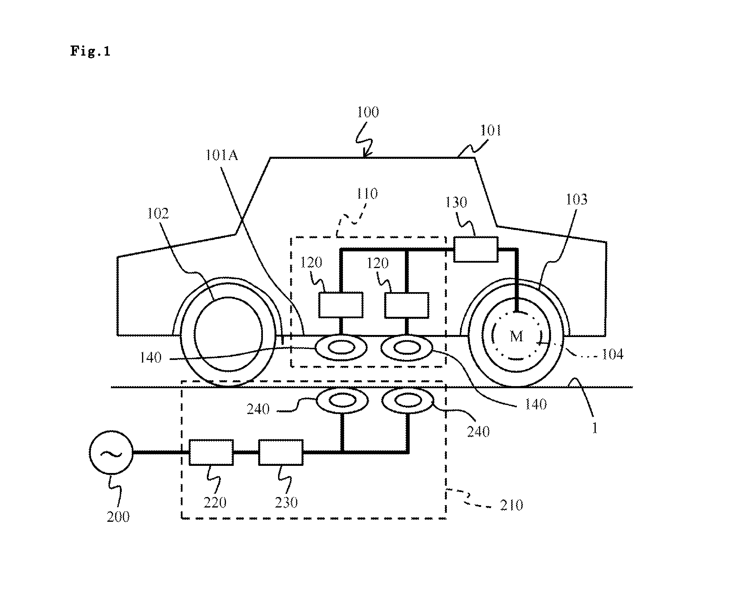
[0029]A first embodiment will be described using FIGS. 1 and 2. FIG. 1 shows an example in which a non-contact charging apparatus for a mobile body is provided in an electric car 100 as the “mobile body”.

[0030]The electric car 100, for example, comprises a car body 101, a front wheel 102, a rear wheel 103, an electric motor 104, a steering device, an illumination device, and an air conditioner (none of which is shown in the drawing). This embodiment shows a case of rear-wheel drive, and the electric motor 104, for example, is provided inside the rear wheel 103.

[0031]The configuration of the electric car 100 is an example, and the electric car 100 may be a front-wheel-drive system, or may be driven using all four wheels. Also, the present invention may be applied to a mobile body such as an electric truck, an electric motorcycle, an electric wheelchair, and an electrically operated single-passenger mobile body (a so-called personal mobility device).

[0032]A plurality of power-receivin...

embodiment 2

[0043]A second embodiment will be described using FIG. 3. The following embodiments, to include this embodiment, are equivalent to variations of the first embodiment, and as such, the descriptions will focus on the differences with the first embodiment.

[0044]A power-receiving device 110A of this embodiment connects a plurality of power-receiving coils 140 and AC-DC converters 120 in series and stores received electric power in the secondary battery 130. A description will be given by assigning a reference sign 142 to power-receiving coils connected in series, and a reference sign 122 to AC-DC converters connected in series.

[0045]This embodiment, being configured like this, achieves the same operational advantage as the first embodiment. In addition, since each power-receiving coil 140 is connected in series in this embodiment, it is possible to obtain the desired voltage value by increasing the charging voltage to the secondary battery 130.

embodiment 3

[0046]A third embodiment will be described using FIG. 4. A power-receiving device 110B of this embodiment charges the secondary battery 130 by connecting in parallel a group of power-receiving coils 141 and a group of AC-DC converters 121 that are connected in parallel (parallel-connection group) and a group of power-receiving coils 142 and a group of AC-DC converters 122 that are connected in series (series-connection group).

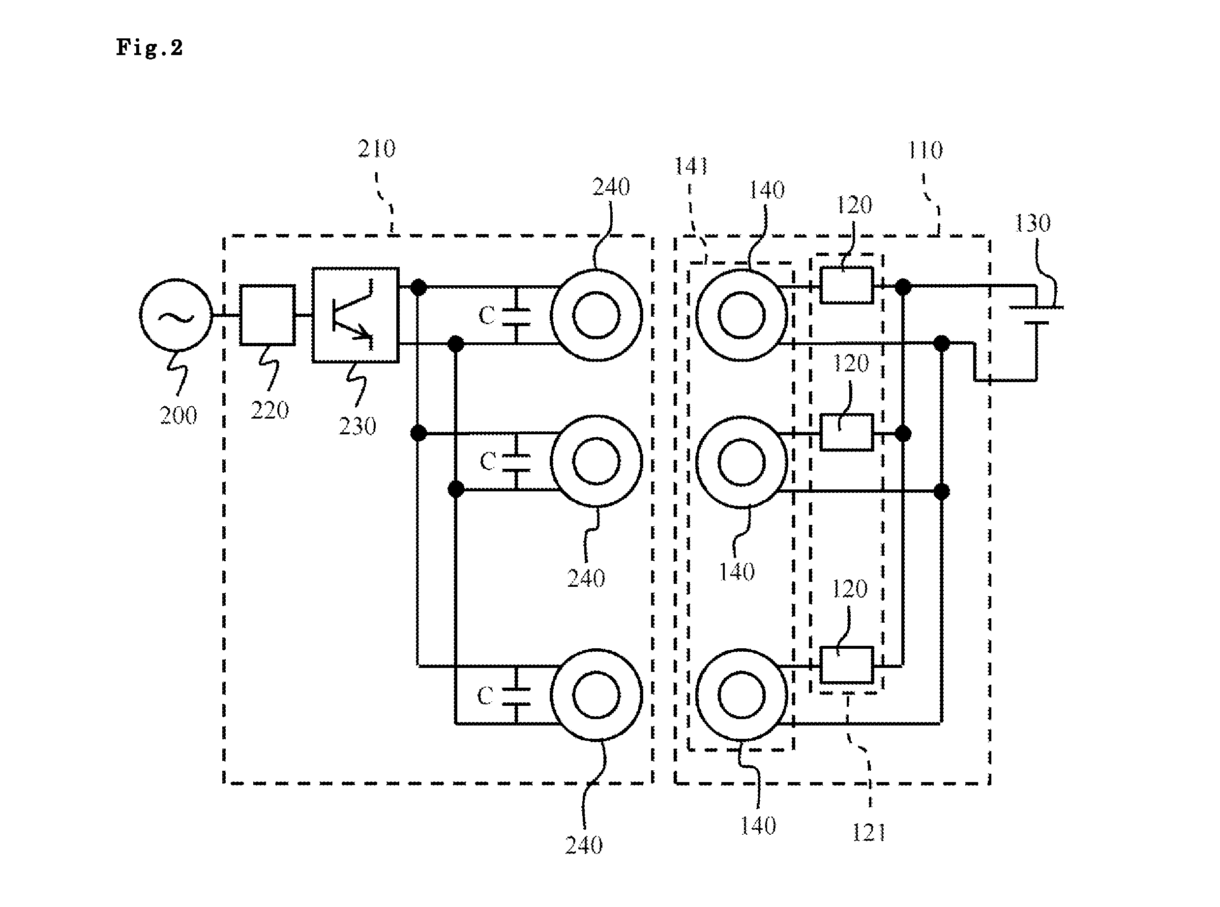
[0047]Focusing on the power-transmitting device 210, with the exception of the fact that the number of power-transmitting coils 240 and the number of resonance capacitors C have increased in proportion to the increase in the number of power-receiving coils 140 of the power-receiving device 110B, the configuration is the same as that of the power-transmitting device 210 described in the first embodiment.

[0048]This embodiment, being configured like this, achieves the same operational advantage as the first embodiment. In addition, in this embodiment, it is possib...


PUM


Abstract

A non-contact charging apparatus for a mobile body has a power-receiving device disposed in an electric car, and a power-transmitting device disposed in a manner of non-contact with the power-receiving device. The power-receiving device has a plurality of power-receiving coils distributively arranged in prescribed locations of the car to receive external electric power. The power-transmitting device has a plurality of power-transmitting coils arranged in prescribed locations outside of the electric car corresponding to the plurality of power-receiving coils to transmit electric power. The non-contact charging apparatus for a mobile body transmits electric power in a non-contact manner from the plurality of power-transmitting coils to the plurality of power-receiving coils and charges a secondary battery. Since a plurality of power-receiving coils are provided, electric power can be transmitted efficiently even when there are installation-space or installation-shape constraints.

Description

BACKGROUND OF THE INVENTION[0001]1. Field of the Invention[0002]The present invention relates to a non-contact charging apparatus for a mobile body and a non-contact charging method for a mobile body.[0003]2. Description of the Related Art[0004]Various types of electrically operated mobile bodies, such as electric cars, electric buses, electric trucks, and electric motorcycles have been proposed in line with an increase in environmental awareness and the development of secondary battery and electric motor technologies. These electrically operated mobile bodies charge a secondary battery, and drive an electric motor using power drawn from the secondary battery to achieve propulsion.[0005]A method for charging the secondary battery by connecting an electric cable to the secondary battery, and a method for charging the secondary battery using a non-contact mode are known. The work involved in the method that uses the electric cable is a nuisance, and as such, the development of a non-c...

Claims


Application Information

Patent Timeline
IPC IPC(8): B60L11/18H02J7/00
CPCB60L11/182Y02T90/14Y02T10/7072B60L53/122B60L53/126H02J2310/48Y02T10/70H02J50/402H02J50/12Y02T90/12B60L53/12H02J7/00
Inventor IMAZU, SHINTOHMA, TAKANORITACHIKAWA, MAKOTOBABA, ATSUSHIKATAYAMA, TOSHIO
Owner HITACHI LTD
Why Eureka
Try Eureka