Network communication system and network communication method

a network communication and network communication technology, applied in the field of communication technology, can solve the problems of increasing memory costs, increasing storage space, and increasing the cost of edge network elements, so as to reduce storage space, reduce storage capacity, and reduce cost

Active Publication Date: 2014-05-01
INVENTEC PUDONG TECH CORPOARTION +1
View PDF8 Cites 15 Cited by
  • Summary
  • Abstract
  • Description
  • Claims
  • Application Information

AI Technical Summary

Benefits of technology

[0018]In view of the above, in the network communication system described in embodiments of the disclosure, each virtual machine is connected to the physical switch through the virtual switch disposed inside the physical machine, so that the physical switch is configured for achieving frame transferring of the cloud network by only requiring to record a machine address of the virtual switch in the physical machine connected to the physical switch. Therefore, by effectively reducing the storage space, for recording the machine addresses, in the physical switch, a manufacturer can select a memory having lower storage capacity to setup a physical switch, thereby reducing the cost.

Problems solved by technology

This is rather expensive.
Nevertheless, edge network elements still require significant memory space.
Therefore, as the number of virtual machines increases, memory costs increase because more network addresses need to be recorded.

Method used


Image

  • Network communication system and network communication method
  • Network communication system and network communication method
  • Network communication system and network communication method

Examples


first embodiment

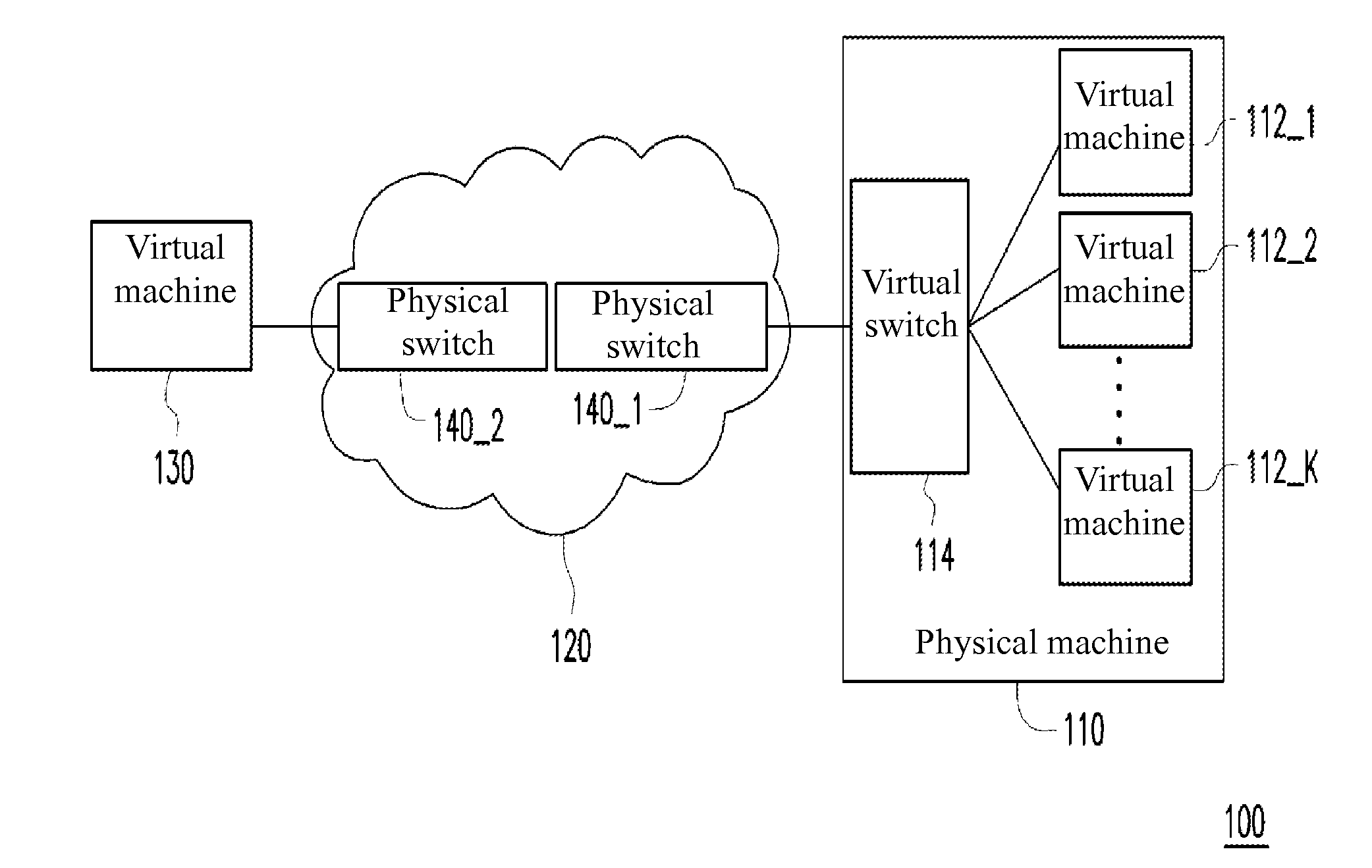
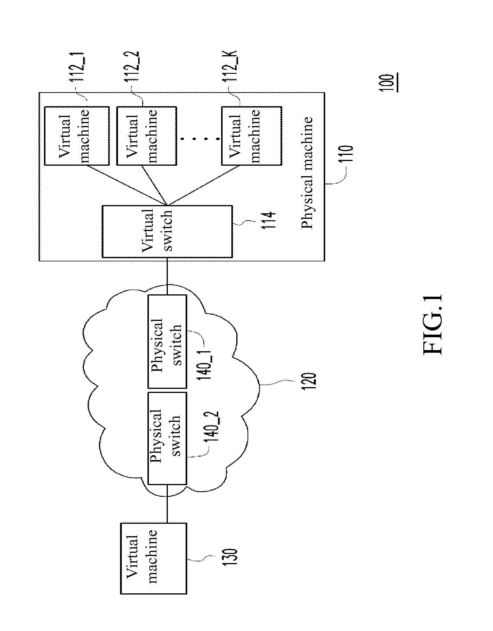
[0026]FIG. 1 is a block diagram of a network communication system according to the disclosure. A network communication system 100 comprises a physical machine 110 and a cloud network 120. The physical machine 110 comprises a virtual switch 114 and virtual machines 112_1-112_K (K is a positive integer). Each of the virtual machines 112_1-112_K is connected to the virtual switch 114. In this and some other embodiments, the physical machine 110 is a server in a common cloud network. Moreover, the virtual machines 112_1-112_K are implemented by software of, for example, VMWare, Xen, Kernel based Virtual Machine (KVM) and VirtualBox.

[0027]The cloud network 120 comprises physical switches 140_1 and 140_2. In this and some other embodiments, the physical switches 140_1 and 140_2 are switches in a common network, or switches such as ToRs. The virtual machines 112_1-112_K located in the physical machine 110 are connected to the physical switch 140_1 through the virtual switch 114, and are fu...

second embodiment

[0037]FIG. 3 is a block diagram of a network communication system 300 according to the disclosure. Each virtual machine in physical machines 110_1-110_R (R is a positive integer) is connected to the physical switch 140_2 respectively through virtual switches 114_1˜114_R. For example, in the physical machine 110_1, virtual machines 112_1_1-112_1_Q (Q is a positive integer) are connected to the physical switch 140_2 through the virtual switch 114_1. In the physical machine 110_R, virtual machines 112_R 1-112_R_P (P is a positive integer) are connected to the physical switch 140_2 through the virtual switch 114_R.

[0038]In this and some other embodiments, the physical machines 110_1-110_R are implemented by a blade server respectively. A plurality of blade servers further form a rack mount server host, and are connected the cloud network 120 through the physical switch 140_2 (that is, the ToR).

[0039]The physical switch 140_2 in the cloud network 120 is connected to the physical switch 1...


PUM


Abstract

A network communication system comprises a cloud network and at least one physical machine. The cloud network comprises at least one physical switch. Each the physical machine comprises a plurality of virtual machines and a virtual switch. Each of the virtual machines is connected to the at least one physical switch in the cloud network through the virtual switch. The virtual switch encapsulates a destination machine address of an egress frame sent by the virtual machines, attaches a destination switch address to the egress frame to be forwarded to the at least one physical switch, and receives and analyzes an ingress frame obtained from the at least one physical switch, so as to convert the destination switch address of the ingress frame to the destination machine address, for forwarding the ingress frame to one of the virtual machines.

Description

CROSS-REFERENCE TO RELATED APPLICATIONS[0001]This non-provisional application claims priority under 35 U.S.C. §119(a) on Patent Application No(s). 201210422005.4 filed in China, P.R.C. on 29 Oct. 2012, the entire contents of which are hereby incorporated by reference.BACKGROUND OF THE INVENTION[0002]1. Technical Field of the Invention[0003]The disclosure relates to a communication technology, more particularly to a network communication system and a network communication method thereof.[0004]2. Description of the Related Art[0005]With the growth of the computer technology and the Internet, cloud computing applications are increasingly popular. In a cloud operation network, a user is able to use resources for calculation, data access and storage provided by the cloud operation without needing to know the location and other details of infrastructures for calculation. A device having lower operation capability (for example, a cell phone) is able to process data by using the resources o...

Claims


Application Information

Patent Timeline
Patent Type & Authority Applications(United States)
IPC IPC(8): H04L12/56H04L49/111
CPCH04L45/7457H04L49/70H04L49/3009H04L45/74591
Inventor TSENG, JENN-HUEIWU, SHIH-HAOWU, YI-KUANLIU, TE-YEN
Owner INVENTEC PUDONG TECH CORPOARTION
Why Eureka
Try Eureka