X-ray detector and x-ray diffraction device

a detector and x-ray technology, applied in the direction of material analysis using wave/particle radiation, optical radiation measurement, instruments, etc., can solve the problems of cumbersome change work, disturbing quick measurement, and remarkably large x-ray detector size, and the scan range of the x-ray detector must be restricted

Inactive Publication Date: 2014-05-01
RIGAKU CORP
View PDF7 Cites 3 Cited by
  • Summary
  • Abstract
  • Description
  • Claims
  • Application Information

AI Technical Summary

Benefits of technology

[0018]According to the above construction, the X-ray detection based on 2θ-rotation can be performed by the first X-ray detection unit, and the X-ray detection based on χ-rotation can be performed by the second X-ray detection unit. Accordingly, both of the X-ray diffraction measurement based on 2θ-rotation and the in-plane diffraction measurement based on χ-rotation can be easily and rapidly performed without exchanging the X-ray detector and without providing any rotating mechanism for the X-ray detector itself.
[0028]As described above, according to the present invention, both of the X-ray diffraction measurement based on 2θ-rotation and the in-plane diffraction measurement based on χ-rotation can be easily and quickly performed without exchanging the X-ray detector and without providing any rotating mechanism for the X-ray detector itself.

Problems solved by technology

Accordingly, when the X-ray detector 102 which is configured so that plural slender unit detection areas 103 are arranged in parallel to one another like the silicon strip detector is applied to the conventional X-ray diffraction device, the arrangement (orientation) of the X-ray detector 102 must be changed between the X-ray diffraction measurement based on 2θ-rotation and the in-plane diffraction measurement every time, and this changing work is cumbersome and disturbs quick measurement.
However, the disclosed construction is merely conceptual, and when it is applied to an actual device, incorporation of a rotating mechanism into an X-ray detector makes the X-ray detector remarkably larger in size because the X-ray detector itself is originally large in size and heavy in weight.
Therefore, there may occur such a problem that the scan range of the X-ray detector must be restricted to avoid interference with surrounding constituent elements.

Method used


Image

  • X-ray detector and x-ray diffraction device
  • X-ray detector and x-ray diffraction device
  • X-ray detector and x-ray diffraction device

Examples


Embodiment Construction

[0040]Embodiments according to the present invention will be described hereunder with reference to the drawings.

[Construction of X-Ray Detector]

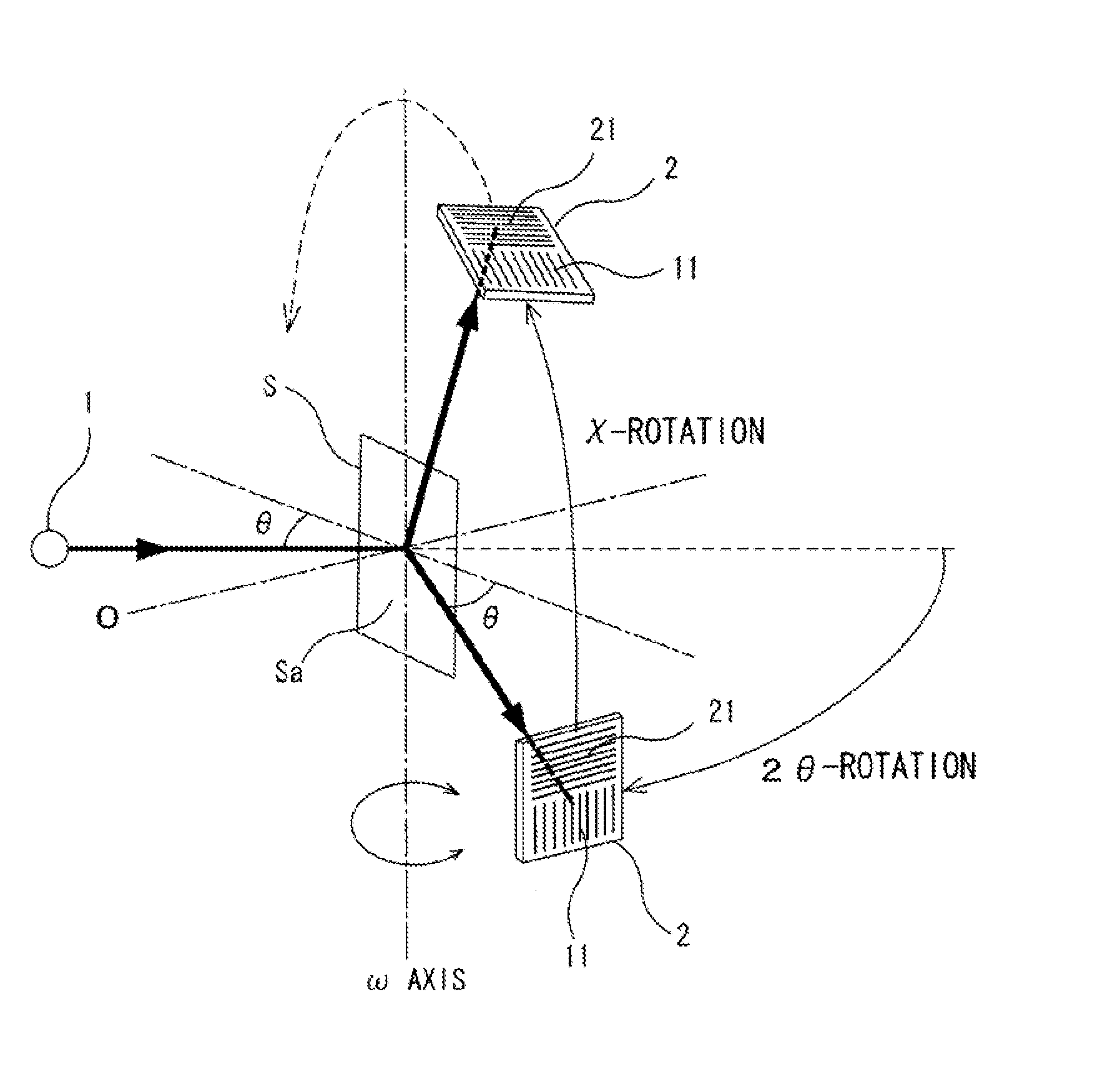
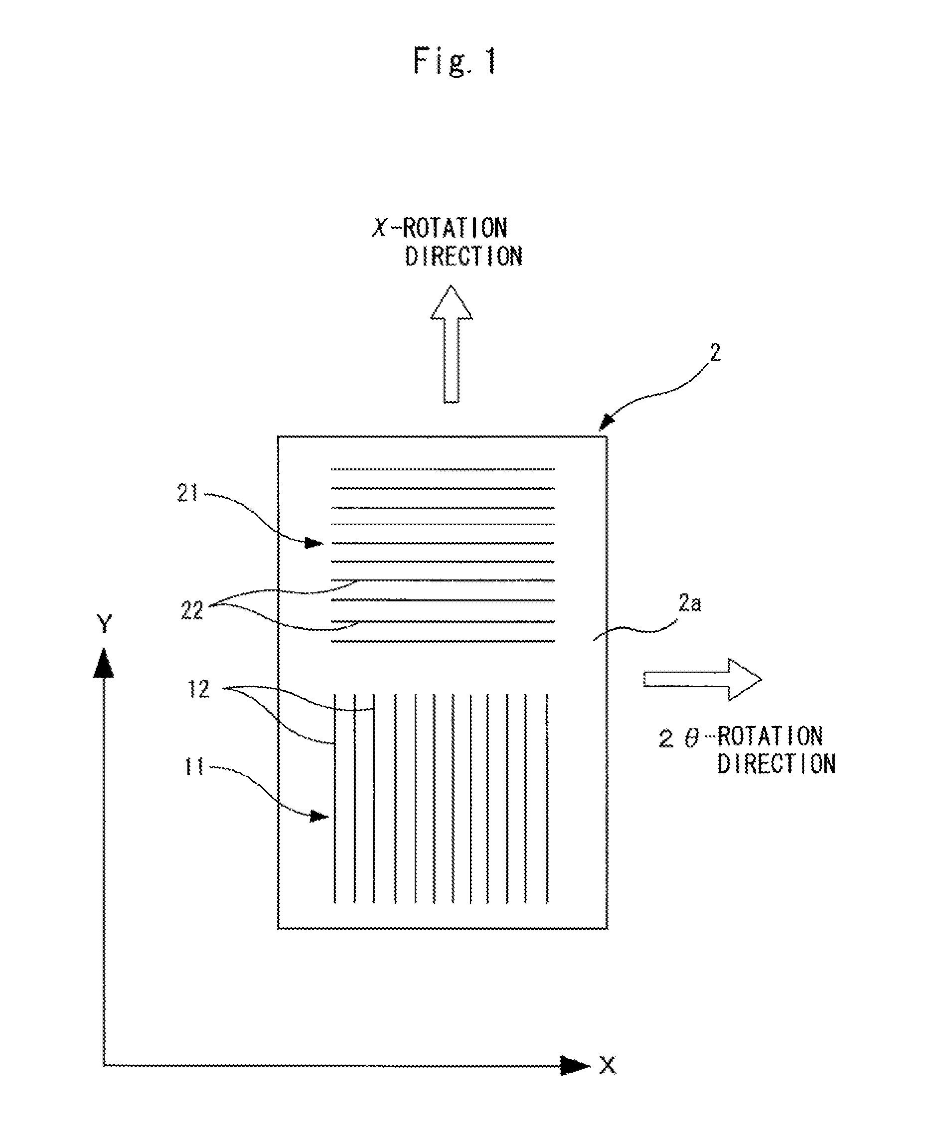
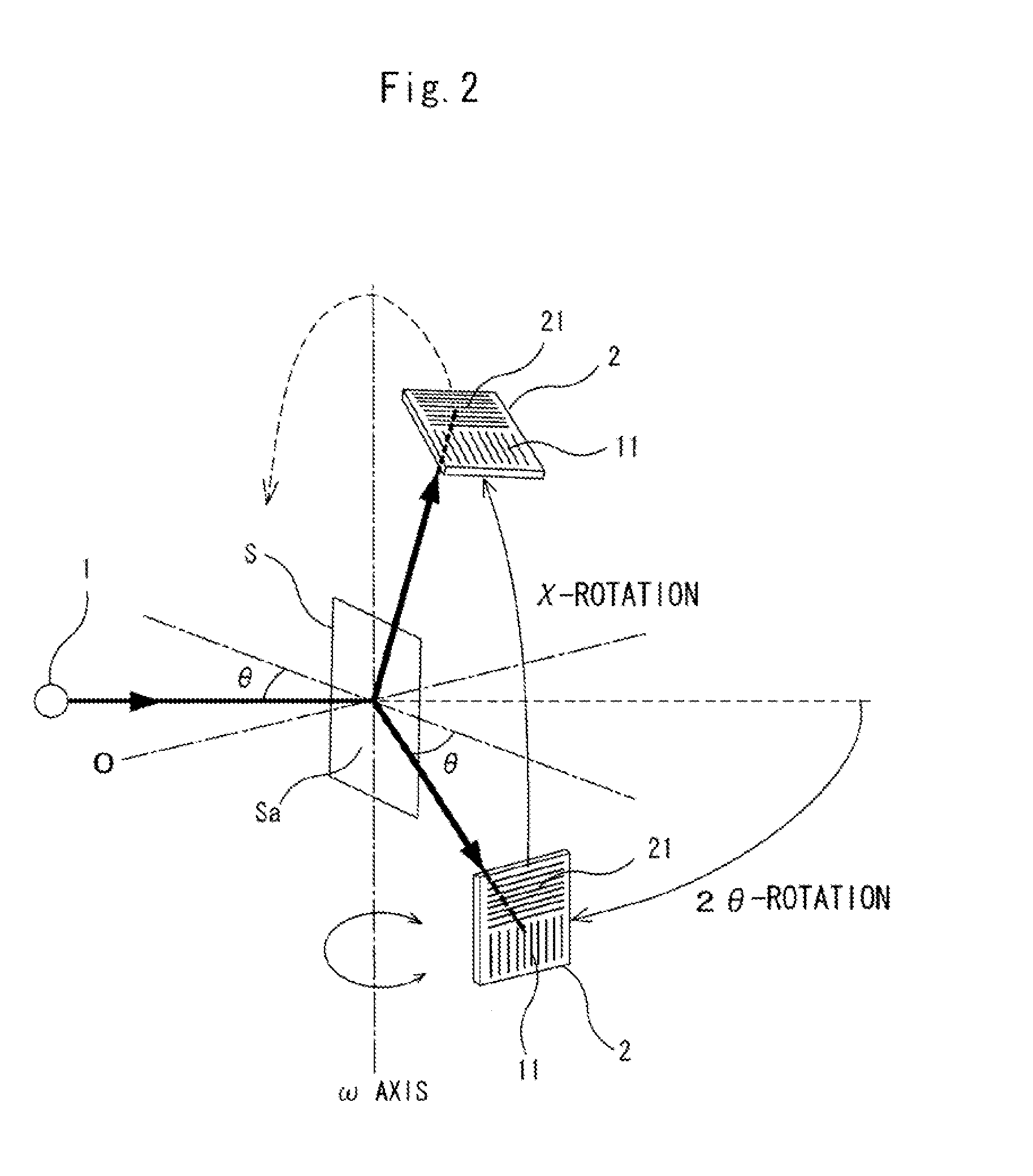
[0041]First, the construction of an X-ray detector according to an embodiment of the present invention will be described with reference to FIG. 1.

[0042]The X-ray detector 2 shown in FIG. 1 has a first X-ray detection unit 11 having plural strips 12 which form slender unit measurement areas and are arranged in parallel to one another (side by side) in an X-direction (first direction), and a second X-ray detection unit 21 having plural strips 22 which form slender unit measurement areas and are arranged in parallel to one another (side by side) in a Y-direction (second direction) like the first X-ray detection unit 11. Here, the X-direction (first direction) and the Y-direction (second direction) are orthogonal to each other.

[0043]The X-ray detector of this embodiment is configured by applying the silicon strip detector as shown in FIGS. 8 and...


PUM

PropertyMeasurementUnit
aaaaaaaaaa
areasaaaaaaaaaa
2θ-aaaaaaaaaa

Abstract

A silicon strip detector having a first X-ray detection unit having plural strips arranged in parallel to one another in a first direction, and a second X-ray detection unit having plural strips arranged in parallel to one another in a second direction orthogonal to the first direction is used as an X-ray detector. The X-ray detector is mounted in an X-ray diffraction device while the first direction is matched with the tangential direction of 2θ-rotation, and the second direction is matched with the tangential direction of χ-rotation for executing in-plane diffraction measurement.

Description

FIELD OF THE INVENTION[0001]The present invention relates to an X-ray diffraction device in which both of normal X-ray diffraction measurement based on 2θ-rotation and in-plane diffraction measurement can be performed, and an X-ray detector suitable for the X-ray diffraction device.BACKGROUND OF THE INVENTION[0002]A Silicon Strip Detector (SSD) is known as an X-ray detector applicable to X-ray diffraction measurement. As shown in FIG. 8, a conventional silicon strip detector is configured so that strip-shaped p+-type semiconductors are formed on the surface of an n-type semiconductor and an n+-type semiconductor is disposed at the back surface side of the n-type semiconductor, for example. A sufficient inverse bias voltage is applied between each p+-type semiconductor and the n+-type semiconductor to generate a depletion layer in an n-type semiconductor surface portion. Accordingly, each strip-shaped p+-type semiconductor and the n-type semiconductor form p-n junction, whereby each ...

Claims


Application Information

Patent Timeline
Patent Type & Authority Applications(United States)
IPC IPC(8): G01N23/207G01T1/16
CPCG01N23/207G01T1/16G21K1/06G01N23/20G01N23/20008G01N23/201G01T1/24G01T1/243
Inventor MATSUSHITA, KAZUYUKIKURIBAYASHI, MASARU
Owner RIGAKU CORP
Why Eureka
Try Eureka