Manufacturing method of battery pack

a manufacturing method and battery pack technology, applied in the direction of secondary cell servicing/maintenance, sustainable manufacturing/processing, instruments, etc., can solve problems such as damage to separators

Active Publication Date: 2014-05-08
TOYOTA JIDOSHA KK
View PDF5 Cites 16 Cited by
  • Summary
  • Abstract
  • Description
  • Claims
  • Application Information

AI Technical Summary

Benefits of technology

[0016]In a battery pack in which the maximum restraint contact pressure Pd is 0.3 to 15.5 MPa, inclusive, by applying the maximum compression contact pressure Pc that is slightly higher than this maximum restraint contact pressure Pd, an effect is able to be suitably obtained in which workability when assembling the battery pack is able to be improved, and only a single cell in which a short may occur in the future due to conductive foreign matter is able to be differentiated by a short-circuit test in a short period of time.

Problems solved by technology

As described in Japanese Patent Application Publication No. 2001-236985 (JP 2001-236985 A), it is expected that when conductive foreign matter present in the electrode body of a single cell is large enough to possibly cause a short when the battery pack is stored or used in the future, this foreign matter may pass through the separator when the single cell is supercompressed at the compression contact pressure, and a positive electrode plate and a negative electrode plate of the single cell may become electrically connected via this foreign matter, causing a short.
However, if the compression contact pressure described above is too high, even if the conductive foreign matter is small, it will damage the separator.
It is also know known that if an extended period of time passes while the battery pack is in a state in which the maximum restraint contact pressure is applied to such damaged single cells (i.e., if the single cells that are damaged in this way continue to be restrained by the restraining member at the maximum restraint contact pressure), the foreign matter may pass through the separator, and the positive and negative electrode plates may become electrically connected via this foreign matter, causing a short.
However, to eliminate this, a short circuit test must be performed for an extended period of time after the battery pack is assembled, which is unrealistic.

Method used


Image

  • Manufacturing method of battery pack
  • Manufacturing method of battery pack
  • Manufacturing method of battery pack

Examples


Embodiment Construction

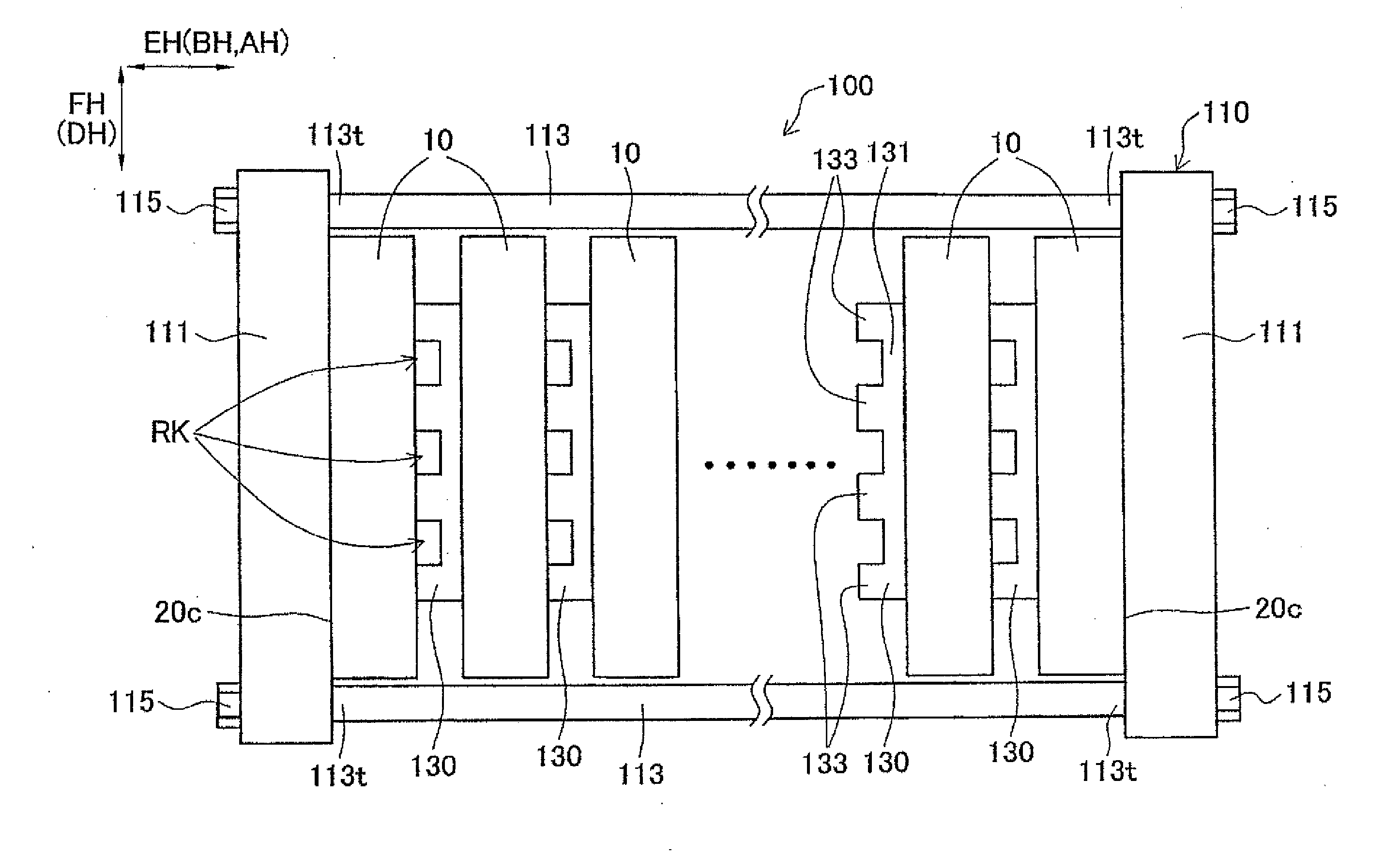
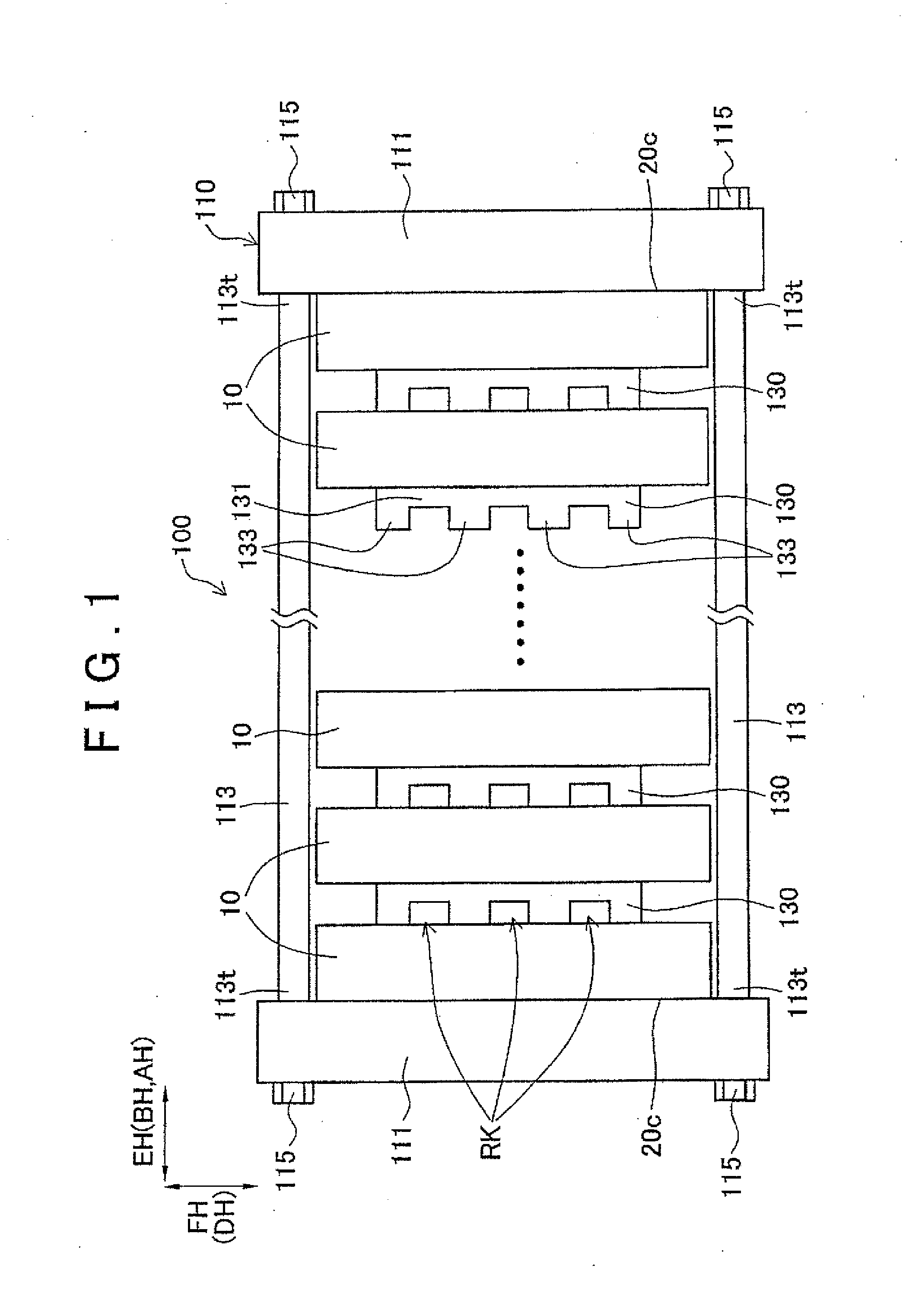
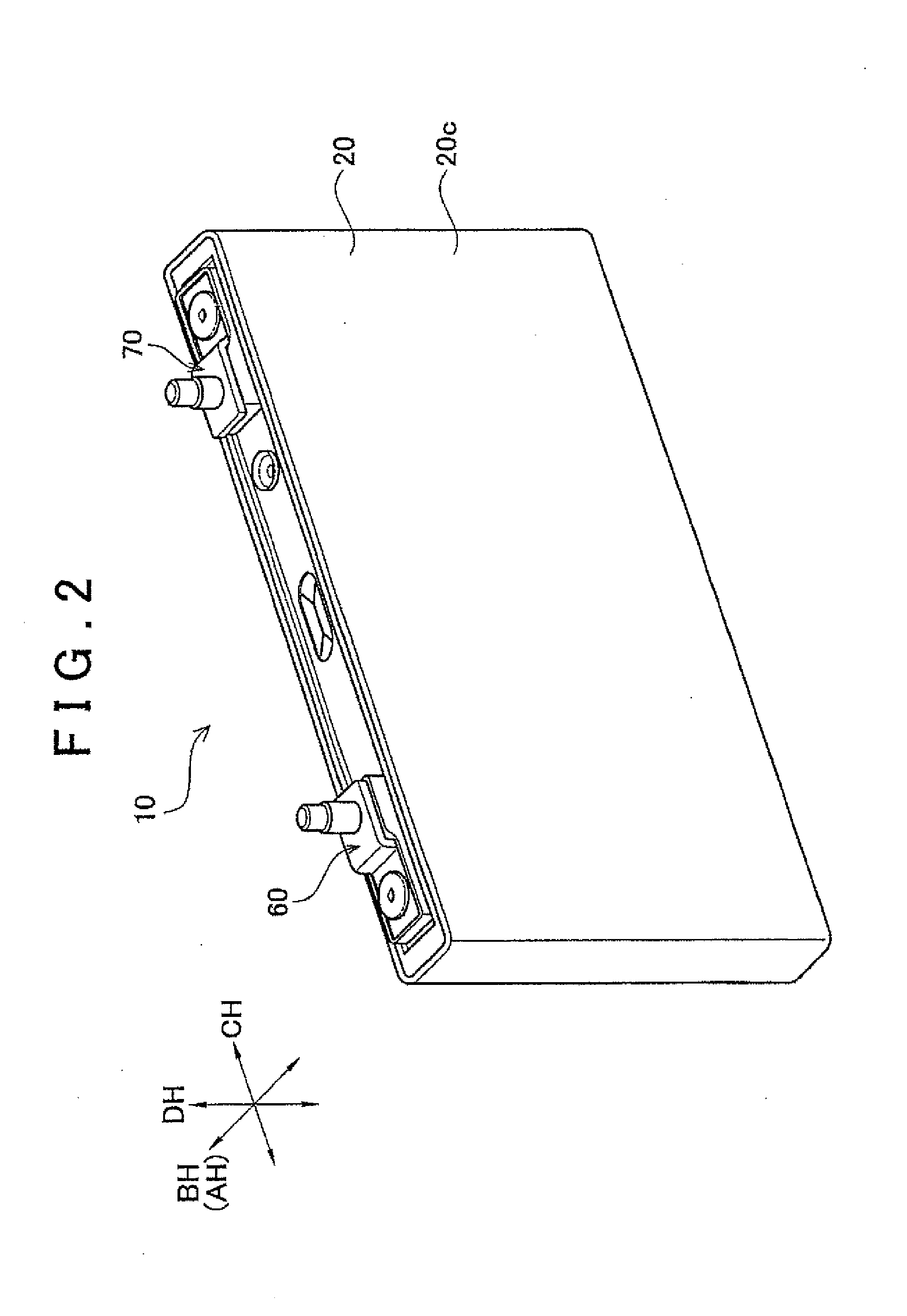
[0024]Hereinafter, example embodiments of the invention will be described with reference to the accompanying drawings. FIG. 1 is a view of a battery pack 100. Also, FIGS. 2 and 3 are views of a single cell 10 that is one of a plurality of single cells 10 that form the battery pack 100, and FIG. 4 is a view of an electrode body 30 that forms the single cell 10. In the description below, a restraining direction EH and a height direction FH of the battery pack 100 are set as the directions shown in FIG. 1, and a thickness direction BH, a width direction CH, and a height direction DH of the single cell 10 are set as the directions shown in FIGS. 1 to 3. This battery pack 100 is mounted in a vehicle such as a hybrid vehicle or an electric vehicle. This battery pack 100 includes a plurality of the single cells 10 arranged in a line, a plurality of spacers 130, one interposed between adjacent single cells 10, and a restraining member 110 that restrains, while pressing against, the single c...


PUM

PropertyMeasurementUnit
contact pressureaaaaaaaaaa
pressure Pcaaaaaaaaaa
compression contact pressure Pcaaaaaaaaaa

Abstract

A manufacturing method of a battery pack includes a restraining process of restraining single cells at a maximum restraint contact pressure Pd of the battery pack in a complete state, after compressing the single cells at a maximum compression contact pressure Pc that satisfies 0.8≦Pd/Pc≦0.9, with respect to the maximum restraint contact pressure Pd; a standing process of then leaving the single cells to stand for a predetermined number of days in an electrically open state; and a short-circuit testing process of then testing for an internal short in the single cells.

Description

INCORPORATION BY REFERENCE[0001]The disclosure of Japanese Patent Application No 2012-244747 filed on Nov. 6, 2012 including the specification, drawings and abstract is incorporated herein by reference in its entirety.BACKGROUND OF THE INVENTION[0002]1. Field of the Invention[0003]The invention relates to a manufacturing method of a battery pack that includes a plurality of single cells each having an electrode body that includes an electrode plate and a separator, and a restraining member that restrains the single cells.[0004]2. Description of Related Art[0005]A battery pack is known in which a plurality of single cells are stacked directly or alternately via spacers, and the restrained by a restraining member.[0006]Normally, when a battery Pack is assembled, the assembled single cells are supercompressed in the stacking direction beforehand to improve workability. This is because workability is improved when the single cells are restrained by a restraining member or the like, as a...

Claims


Application Information

Patent Timeline
Patent Type & Authority Applications(United States)
IPC IPC(8): H01M10/42G01R31/36
CPCG01R31/3641H01M10/4285G01R31/3865H01M10/0404G01R31/52H01M10/0468H01M10/4207Y02E60/10Y10T29/49004Y10T29/49108Y02P70/50G01R31/36H01M10/42H01M10/4214
Inventor IWASE, KOSUKE
Owner TOYOTA JIDOSHA KK
Why Eureka
Try Eureka