A method of starting a turbomachine while reducing thermal unbalance

a turbomachine and thermal unbalance technology, applied in the field of turbomachines, can solve the problems of affecting the operation of the turbomachine, and affecting the reliability of the turbomachin

Active Publication Date: 2014-05-08
SAFRAN HELICOPTER ENGINES
View PDF3 Cites 62 Cited by
  • Summary
  • Abstract
  • Description
  • Claims
  • Application Information

AI Technical Summary

Benefits of technology

[0017]a primary acceleration step during which the starter is operated to increase the speed of rotation of the rotor;
[0021]Since the speed of rotation no longer increases after the primary acceleration step, the thermal unbalance does not produce unacceptable vibration during the primary acceleration step and the thermal homogenization step. Furthermore, during the thermal homogenization step, forced convective exchanges within the engine make temperatures uniform and therefore reduce the thermal unbalance. Thus, when the speed of rotation increases once more during the secondary acceleration state, the thermal unbalance is smaller and no longer generates unacceptable vibration.
[0029]During the thermal homogenization step, it is possible to control the starter so as to keep the speed of rotation of the rotor constant.

Problems solved by technology

Thermal unbalance is a temporary unbalance that occurs in the rotor of a turbomachine after it has been stopped.
The thermal unbalance may be one hundred times greater than the residual unbalance of the rotor.
Thus, while restarting the turbomachine, on passing through critical speeds the thermal unbalance can give rise to strong vibration, which can degrade the reliability of the turbomachine.
Thermal unbalance may also have the consequence of contact being made between the stator and the rotor, which can deteriorate the integrity of the components involved.
Nevertheless, those known solutions present certain drawbacks:not restarting for a certain length of time penalizes the availability of the turbomachine;specific procedures require action to be taken by an operator, e.g. by the pilot for an aeroengine;enlarging clearances between the stator and the rotor is detrimental to the performance of the turbomachine; andadapting the architecture of the engine is detrimental to the weight of the turbomachine.

Method used


Image

  • A method of starting a turbomachine while reducing thermal unbalance
  • A method of starting a turbomachine while reducing thermal unbalance
  • A method of starting a turbomachine while reducing thermal unbalance

Examples


Embodiment Construction

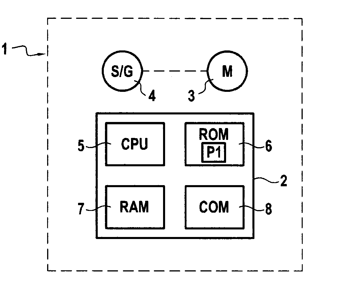
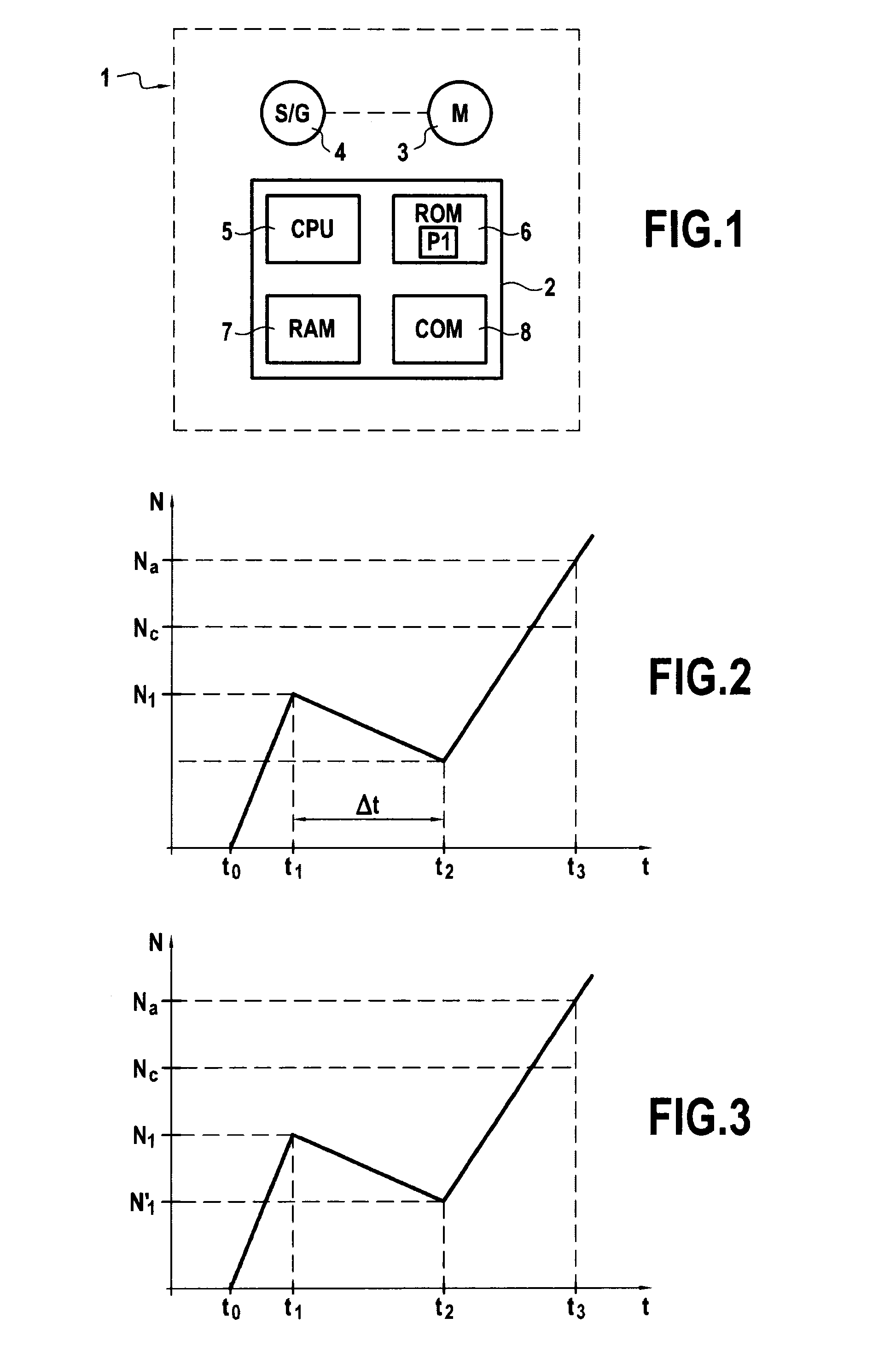
[0039]FIG. 1 shows a turbomachine 1 that comprises an electronic unit 2, an engine 3, and a starter 4. In an embodiment of the invention, the turbomachine 1 is a helicopter turboshaft engine. This type of turboshaft engine is known to the person skilled in the art and it is therefore not described in detail. Nevertheless, the invention is applicable to other types of turbomachine for aircraft, in particular to a turbojet, to a two-spool bypass turbojet, to a turboprop, . . . , or else to industrial turbomachines, . . .

[0040]The engine 3 is a gas turbine engine that includes at least one rotor. Below, the speed of rotation of the rotor is written N. In the above-mentioned situation of a two-spool bypass turbojet, the engine 3 has two rotors and N designates the speed of rotation of one of the two rotors.

[0041]By way of example, the starter 4 is an electric motor coupled to the engine 3 and capable of driving the engine 3 in rotation. The starter 4 may also act as an electricity gener...


PUM


Abstract

A method of starting a turbomachine, performed by an electronic unit, the turbomachine including a gas turbine engine including at least one rotor and a starter to drive the rotor in rotation, the method including: receiving an order to start the turbomachine, and executing in response to receiving the order to start: a primary acceleration during which the starter is operated to increase speed of rotation of the rotor; a thermal homogenization during which the starter is operated to keep the speed of rotation of the rotor constant or to decrease it until a predetermined condition is satisfied; after the predetermined condition is true, a secondary acceleration in which the starter is operated to increase the speed of rotation of the rotor; and an ignition in which ignition of the engine is ordered.

Description

BACKGROUND OF THE INVENTION[0001]The present invention relates to the general field of turbomachines. The present invention relates in particular to taking account of thermal unbalance when starting a turbomachine.[0002]Thermal unbalance is a temporary unbalance that occurs in the rotor of a turbomachine after it has been stopped. Since hot air is lighter than cold air, temperature nonuniformities occur in the air-flow passage, which deform the rotor by a bimetallic effect. The thermal unbalance may be one hundred times greater than the residual unbalance of the rotor.[0003]However, a turbomachine must pass through one or more critical speeds before reaching its operating speed. Thus, while restarting the turbomachine, on passing through critical speeds the thermal unbalance can give rise to strong vibration, which can degrade the reliability of the turbomachine. Thermal unbalance may also have the consequence of contact being made between the stator and the rotor, which can deterio...

Claims


Application Information

Patent Timeline
Patent Type & Authority Applications(United States)
IPC IPC(8): F02C7/26
CPCF02C7/26F01D19/02F02C7/264F02C7/268F05D2260/85F05D2260/96F05D2270/01F05D2270/10Y02T50/60
Inventor MOUZE, YANNBATLLE, FREDERIC FERDINAND JACQUESHAEHNER, EDGARSEGURA, FREDERIC
Owner SAFRAN HELICOPTER ENGINES
Why Eureka
Try Eureka