Raw material vaporizing and supplying apparatus

Inactive Publication Date: 2014-05-08
FUJIKIN INC
View PDF8 Cites 12 Cited by
  • Summary
  • Abstract
  • Description
  • Claims
  • Application Information

AI Technical Summary

Benefits of technology

[0028]The present invention is configured to keep a temperature in the source tank at a set value, and to control the pressure in the internal upper space portion of the source tank by using the automatic pressure regulating device, and to supply a mixed gas from the internal upper space portion of the source tank to the chamber while controlling its flow rate by means of the pressure type flow control system. Thus, the present invention operates differently from the bubbling method because the steam pressure PMo of the raw material steam in the source tank is maintained as saturated steam at a set temperature by heating the raw material in the source tank, and the total pressure Ptank in the internal upper space portion of the source tank is controlled to be at a set value by using the automatic pressure regul

Problems solved by technology

Therefore, it is not possible to directly control the flow rate of the mixed gas G0 by the thermal type mass flow control system 3.
However, in the above-described raw material vaporizing and supplying apparatus of the bubbling method, as well, there still remain many unsolved problems.
First, one problem is due to the fact that because the expensive thermal type mass flow control system 3 is used, not only it is difficult to achieve lowering of the manufacturing cost of the raw material vaporizing and supplying apparatus, it is also necessary to highly accurately control the supply pressure of the carrier gas supplied from the carrier gas source 1 to the thermal type mass flow control system 3, which increases the equipment cost of the decompression unit 2.
Furthermore, there is a problem that it is not possible to directly control the flow rate of the mixed gas G0 by the thermal type mass flow control system 3.
The second problem is due to the fact that because the apparatus adopts the bubbling method, it is difficult to stably supply a raw material steam in the case of a solid raw material, and it is additionally difficult to stably supply a raw material steam in the case of a raw material with low steam pressure, which often makes it unstable to supply a mixed gas to the process chamber.
In other words, the supply of raw materials t

Method used


Image

  • Raw material vaporizing and supplying apparatus
  • Raw material vaporizing and supplying apparatus
  • Raw material vaporizing and supplying apparatus

Examples


Embodiment Construction

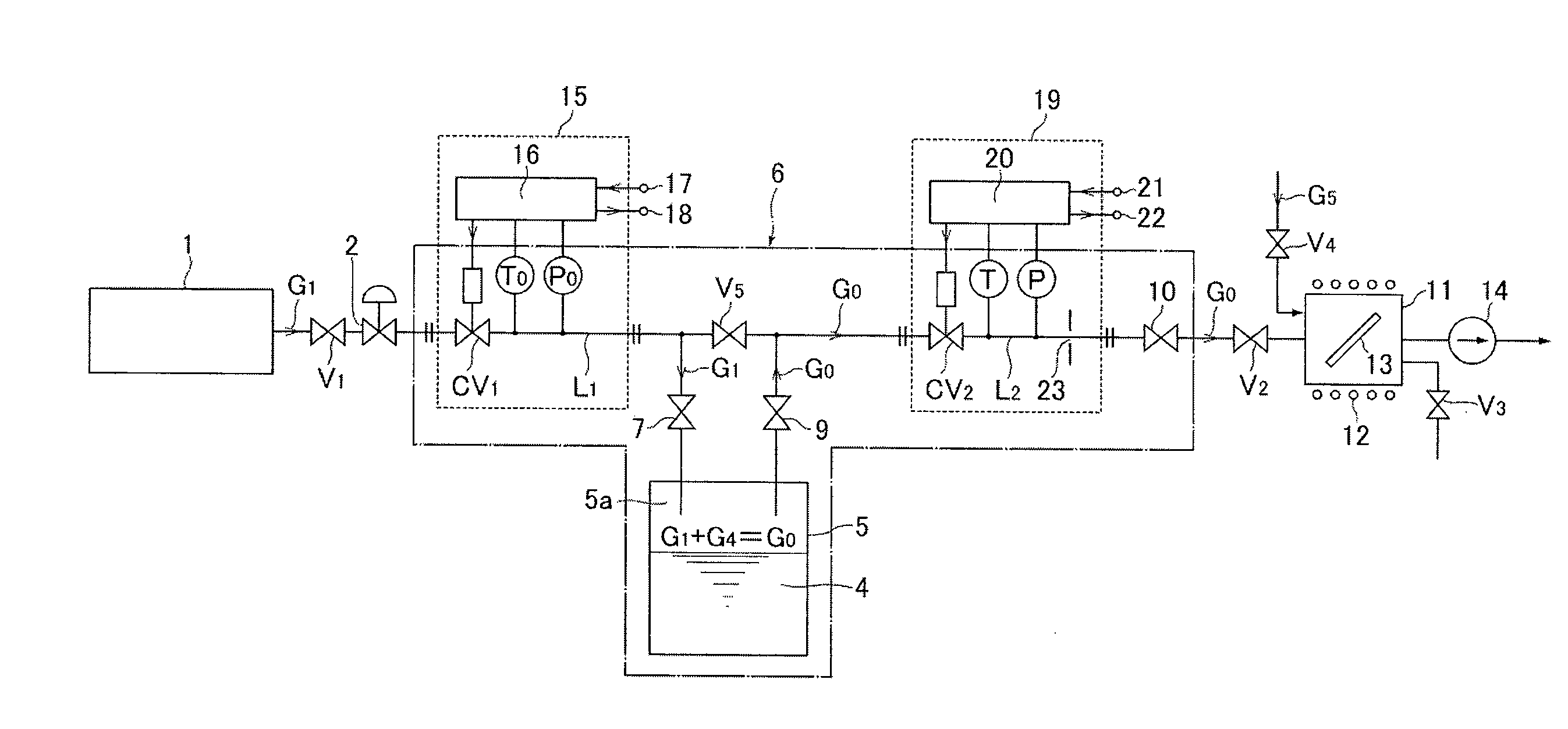
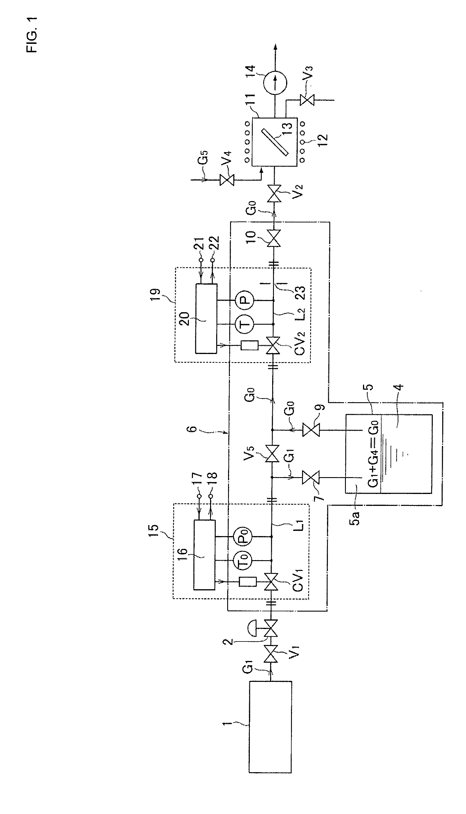
[0038]Hereinafter, an embodiment of the present invention will be described with reference to the drawings, wherein like parts are designated using like references. FIG. 1 illustrates a configuration systematic diagram of a raw material vaporizing and supplying apparatus according to an embodiment of the present invention, wherein the raw material vaporizing and supplying apparatus is composed of a carrier gas supply source 1, a source tank 5 that contains a raw material 4, an automatic pressure regulating device 15 that controls the internal pressure of the source tank 5, a flow control system 19 that regulates a supply flow rate of a mixed gas G0, which is supplied to a process chamber 11, a constant temperature heating unit 6 that heats up the distribution passages of the automatic pressure regulating device 15 and the flow control system 19, the source tank 5, and the like.

[0039]In addition, in FIG. 1, the same reference symbols are given to the same component members as those o...


PUM

PropertyMeasurementUnit
Temperatureaaaaaaaaaa

Abstract

A raw material vaporizing and supplying apparatus includes a carrier gas supply source, a source tank storing raw material, a flow passage supplying carrier gas to an internal upper space portion of the source tank, an automatic pressure regulating device installed on the flow passage, controlling pressure in the internal upper space portion to a set pressure, another flow passage supplying mixed gas (a mixture of raw material steam and carrier gas) from the internal upper space portion to a process chamber, a flow control system installed on this other flow passage, and automatically regulates a flow rate of the mixed gas supplied to the process chamber to a set flow rate, and a constant temperature heating unit that heats the source tank, a portion of the automatic pressure regulating device, a portion of the flow control system, the pipe passage, and the other pipe passage, to a set temperature.

Description

[0001]This is a Continuation-in-Part Application in the United States of International Patent Application No. PCT / JP2012 / 001117 filed Feb. 20, 2012, which claims priority on Japanese Patent Application No. 2011-100446, filed Apr. 28, 2011. The entire disclosures of the above patent applications are hereby incorporated by reference.FIELD OF THE INVENTION[0002]The present invention relates to an improvement in a raw material vaporizing and supplying apparatus of semiconductor manufacturing equipment using so-called “metalorganic chemical vapor deposition” (hereinafter called MOCVD), and, more particularly, relates to a raw material vaporizing and supplying apparatus that is capable of supplying a raw material steam of all raw materials (of not only a liquid raw material but also a solid raw material), or a raw material with low steam pressure, and the raw material vaporizing and supplying apparatus serves to make possible control of a mixture ratio of raw material steam and a carrier ...

Claims


Application Information

Patent Timeline
IPC IPC(8): C23C16/455
CPCC23C16/4481C23C16/45557C23C16/52C23C16/45512Y10T137/7837C23C16/448H01L21/205
Inventor HIDAKA, ATSUSHIHIRATA, KAORUNAGASE, MASAAKIDOHI, RYOUSUKENISHINO, KOUJIIKEDA, NOBUKAZU
Owner FUJIKIN INC
Why Eureka
Try Eureka