Tank overflow pipe system

Inactive Publication Date: 2014-05-08
FLUOR TECH CORP
View PDF7 Cites 9 Cited by
  • Summary
  • Abstract
  • Description
  • Claims
  • Application Information

AI Technical Summary

Benefits of technology

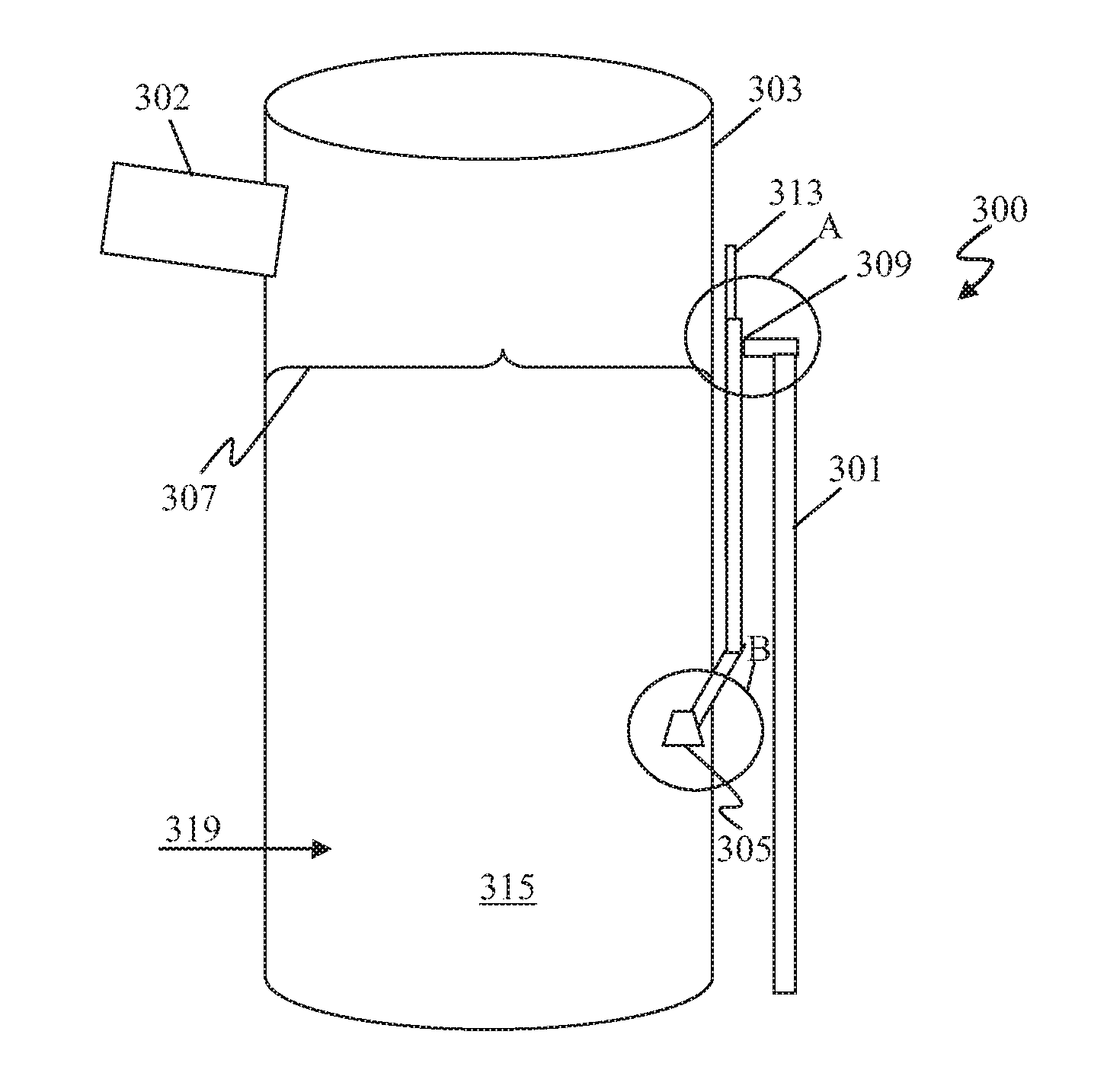
The patent relates to a system for removing excess slurry from a tank and reducing stagnation in the overflow pipe. It introduces air into the tank to oxidize the slurry and uses an overflow pipe with a recirculation conduit to keep the slurry moving. Additionally, an air capture unit is placed at the inlet of the overflow pipe to collect excess oxidation air and make the conditions in the overflow tank similar. The technical effects of the patent are reduced stagnation in the overflow pipe, improved slurry quality, and more efficient gas conditioning systems.

Problems solved by technology

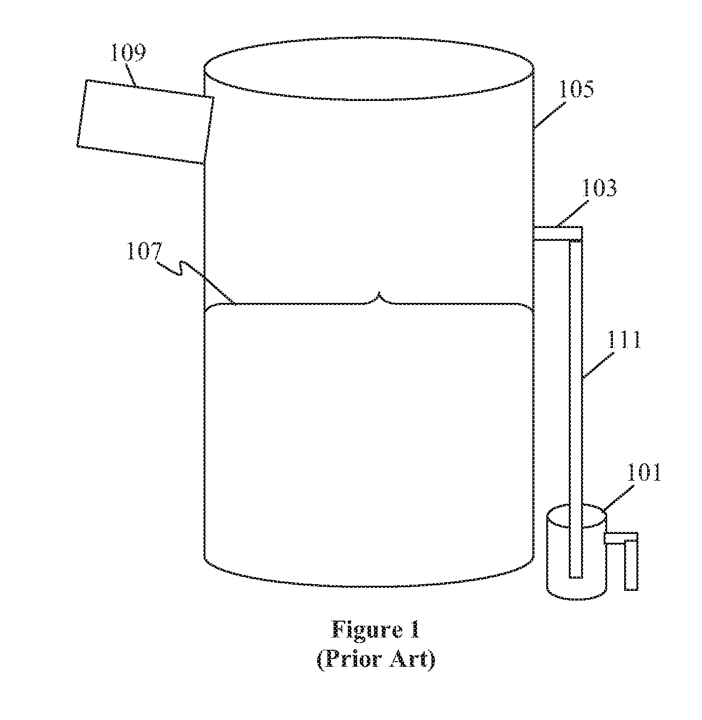
With respect to flue gas desulfitrization systems and other systems having non-atmospheric pressure slurry tanks, overflow systems are critical to prevent flow back into an inlet conduit that could otherwise lead to significant problems.
Limestone forced oxidation systems can be especially problematic because they generally have a two-phase slurry (solid and liquid) and the tank is aerated with air used to oxidize the reaction product of SO2 and CaCO3 into CaSO4.2H2O (gypsum).
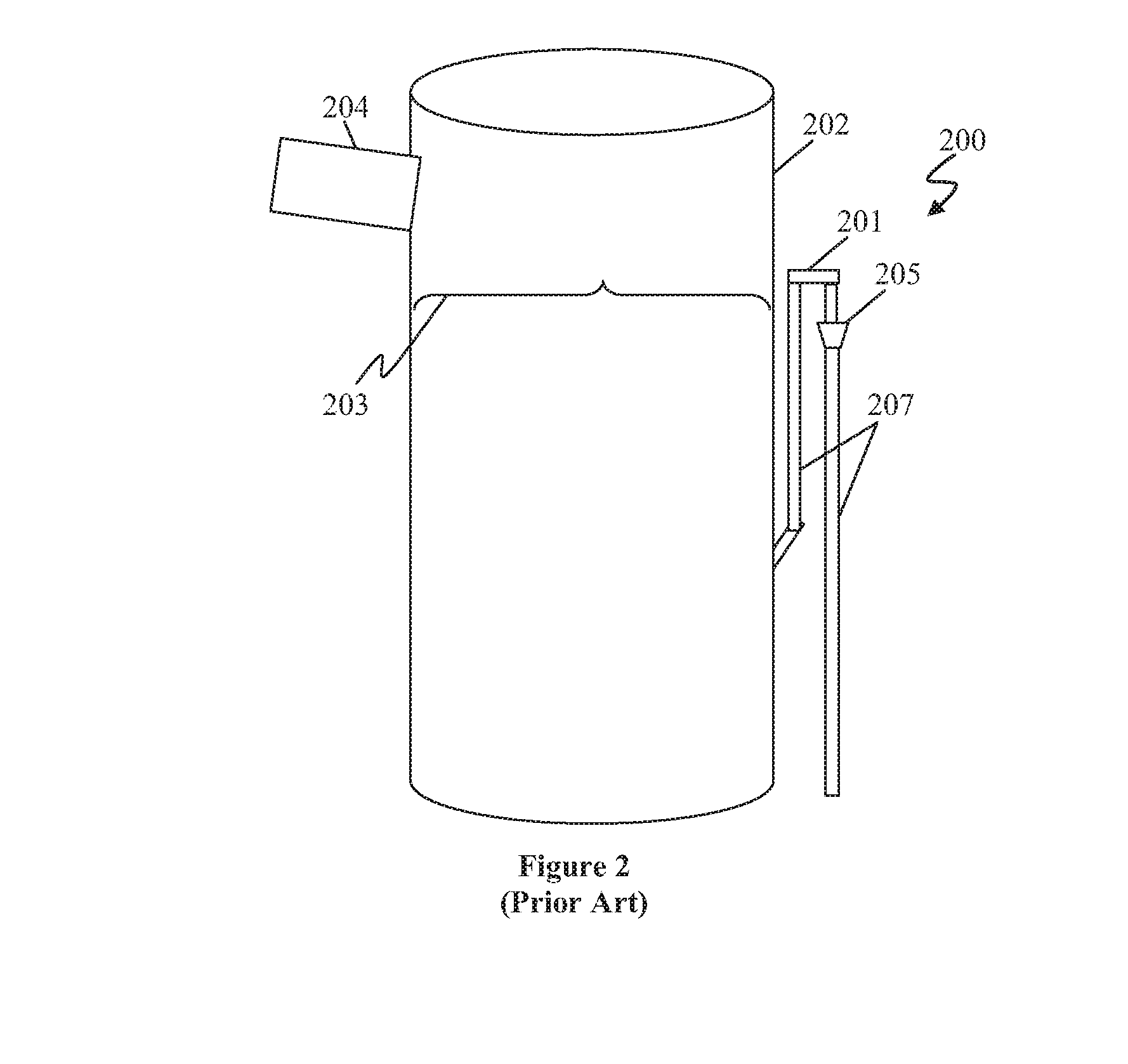
However, such configurations typically have stagnant flow, allowing the solids to settle.
In addition, such configurations fail to account for oxidation air that can lead to formation of froth.
However, such system can be problematic because it may require extensive modification of a typical absorber.
However, such solutions also suffer from one or more disadvantages.

Method used


Image

  • Tank overflow pipe system
  • Tank overflow pipe system
  • Tank overflow pipe system

Examples


Embodiment Construction

[0018]The following discussion provides many example embodiments of the inventive subject matter. Although each embodiment represents a single combination of inventive elements, the inventive subject matter is considered to include all possible combinations of the disclosed elements. Thus if one embodiment comprises elements A, B, and C, and a second embodiment comprises elements B and D, then the inventive subject matter is also considered to include other remaining combinations of A, B, C, or D, even if not explicitly disclosed.

[0019]Unless the context dictates the contrary, all ranges set forth herein should be interpreted as being inclusive of their endpoints and open-ended ranges should be interpreted to include only commercially practical values. Similarly, all lists of values should be considered as inclusive of intermediate values unless the context indicates the contrary.

[0020]As used in the description herein and throughout the claims that follow, the meaning of “a,”“an,” ...


PUM


Abstract

Overflow systems are described for non-atmospheric pressure, slurry tank, which can reduce stagnation of excess flurry in an overflow pipe. In such systems, stagnation of the excess slurry in the overflow pipe is reduced via a recirculation conduit that allows for recirculation of at least a portion of the slurry from the tank. Moreover, an air capture unit collects a portion of an oxidation air from the tank. As a result, the fluid in the overflow system is representative of the aerated slurry within the tank.

Description

[0001]This application claims priority to U.S. provisional application having Ser. No. 61 / 721,772 filed on Nov. 2, 2012. This and all other referenced extrinsic materials are incorporated herein by reference in their entirety. Where a definition or use of a term in a reference that is incorporated by reference is inconsistent or contrary to the definition of that term provided herein, the definition of that term provided herein is deemed to be controlling.FIELD OF THE INVENTION[0002]The field of the invention is overflow systems for non-atmospheric pressure tanks.BACKGROUND[0003]The following description includes information that may be useful in understanding the present invention. It is not an admission that any of the information provided herein is prior art or relevant to the presently claimed invention, or that any publication specifically or implicitly referenced is prior art.[0004]All publications identified herein are incorporated by reference to the same extent as if each i...

Claims


Application Information

Patent Timeline
IPC IPC(8): G05D9/02
CPCG05D9/02B01D53/504B01D53/73B65D90/26Y10T137/8593
Inventor JOHNSON, DENNIS W.
Owner FLUOR TECH CORP
Why Eureka
Try Eureka