Laminator

a technology of laminater and cylinder head, which is applied in the field of laminater, can solve the problems of low cost of production and assembly, and achieve the effect of high reliability, simple and more economical configuration

Inactive Publication Date: 2014-05-08
MONOLITH
View PDF3 Cites 0 Cited by
  • Summary
  • Abstract
  • Description
  • Claims
  • Application Information

AI Technical Summary

Benefits of technology

[0009]Thus, it is an object of the invention to provide a laminator with a temperature display device which is configured much simpler and more economically and which has high reliability.

Problems solved by technology

Due to the simple configuration of the temperature display device, the cost for production and assembly is low.

Method used


Image

  • Laminator
  • Laminator
  • Laminator

Examples


Embodiment Construction

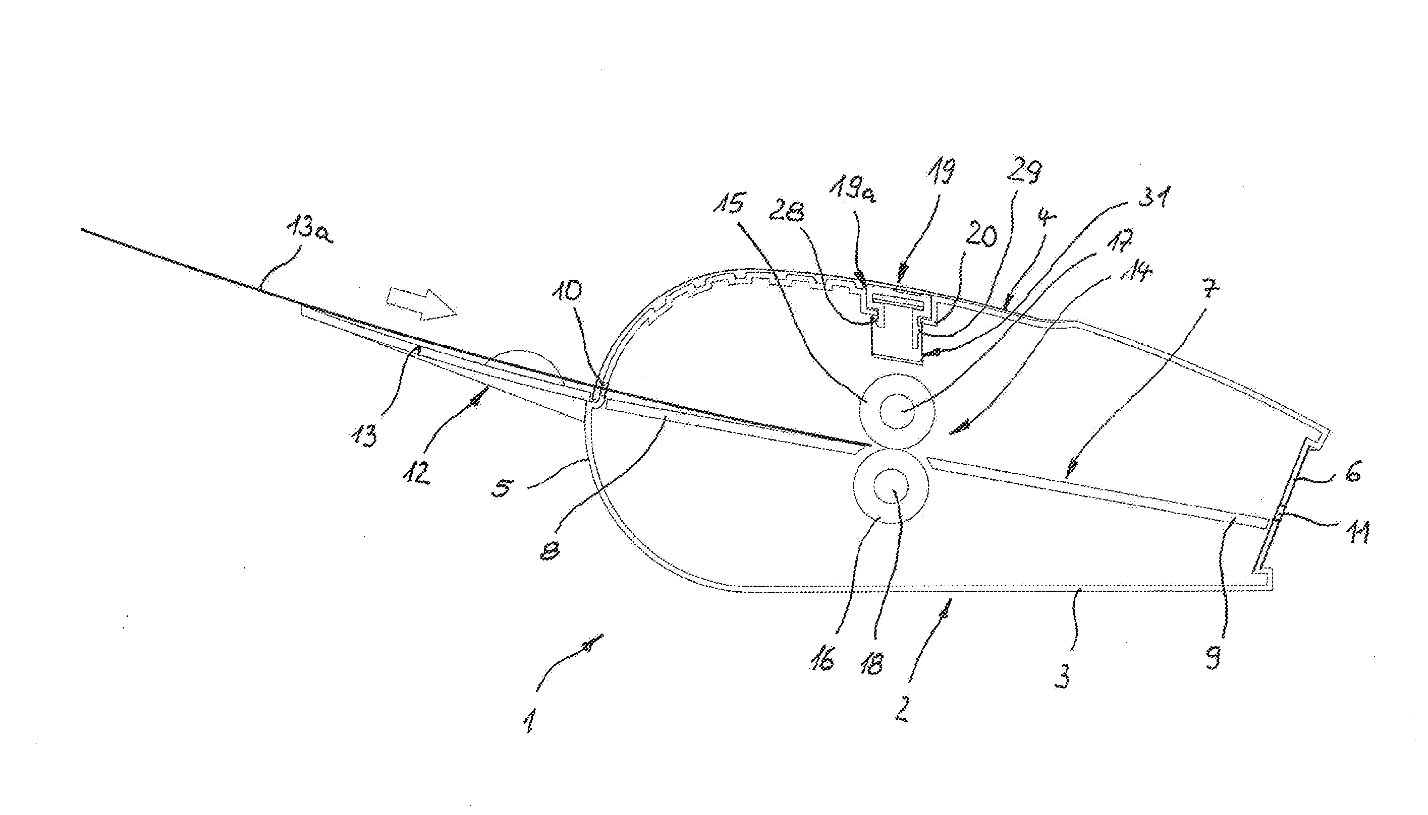
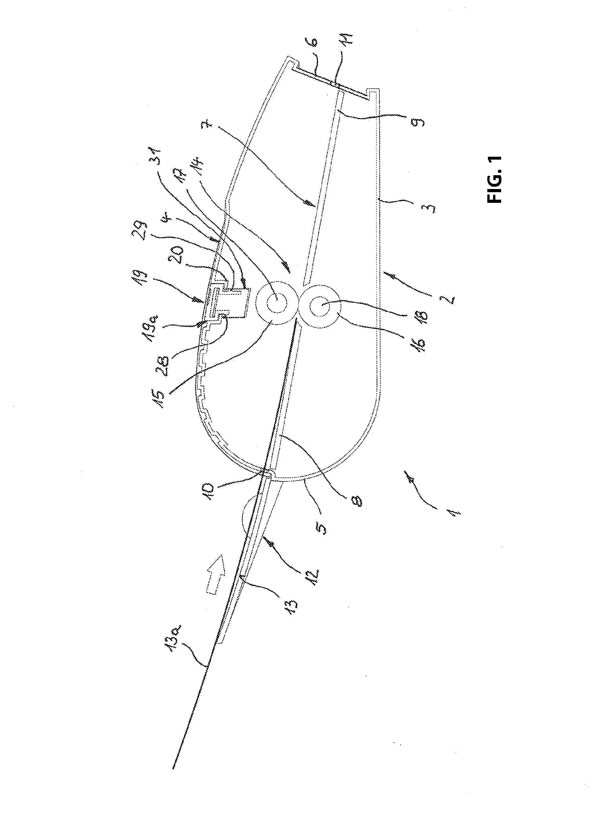
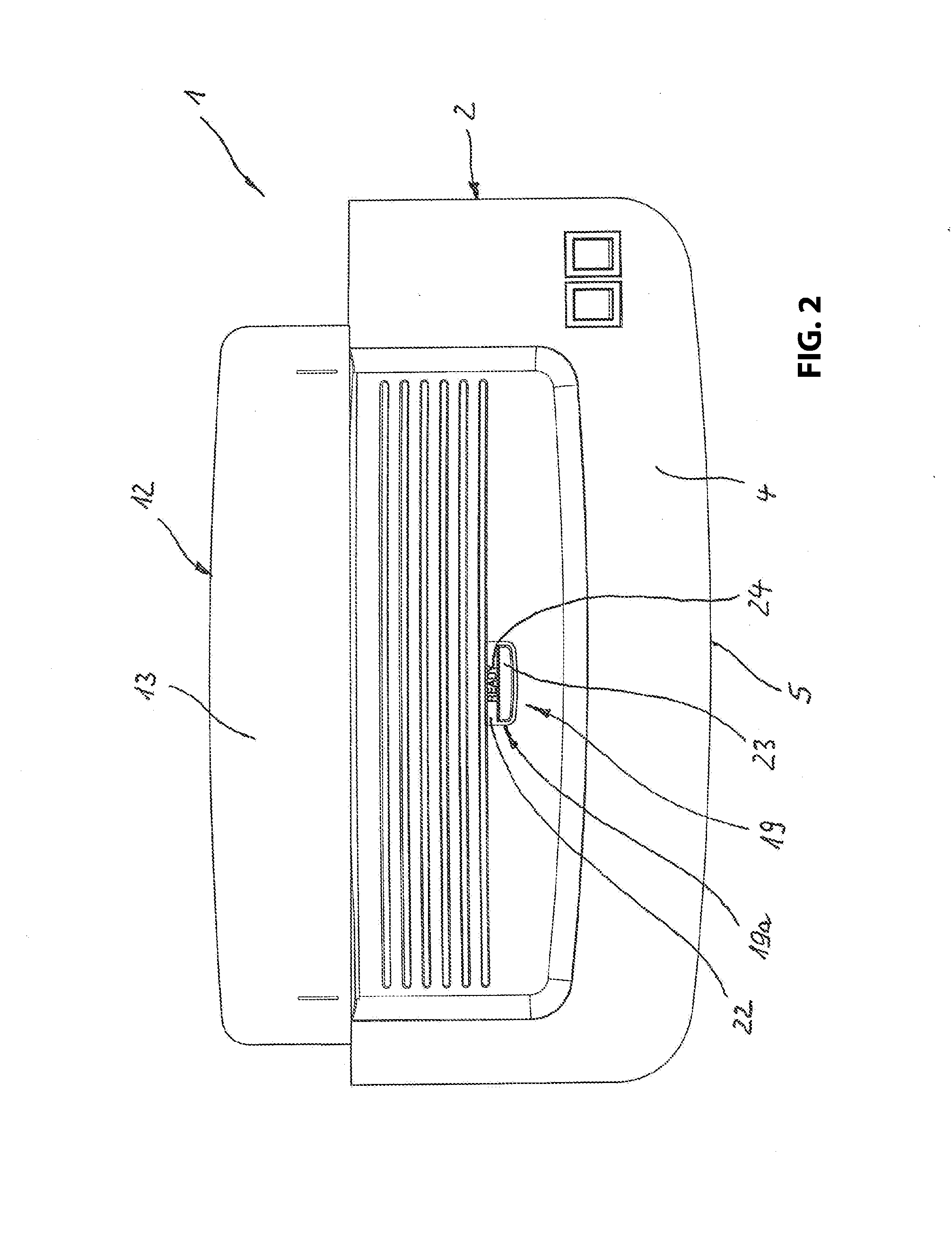
[0026]The laminator 1 illustrated in FIGS. 1 and 2 includes a housing 2 with a flat housing base 3, an upper wall 4 and front- and back walls 5, 6 connecting the housing base and the upper wall, wherein the front wall 5 connects the housing base 3 and the upper wall 4 in an arcuate shape. A slightly downward sloping pass-through channel 7 extends from the front wall 5 to the back wall 6, wherein the bottom side of the pass-through channel is formed by contact plates 8, 9 attached at the laminator. The pass-through channel 7 is defined on the front side by the supply opening 10 in the front wall 5 and defined on the backside by an outlet opening 11 in the rear wall 6.

[0027]A sheet support 12 is mounted at the front wall 5, wherein the top side 13 of the sheet support joins flush at the bottom edge of the supply opening 10 and at the support plate 8. In FIG. 1, the sheet support supports a combination 13a of laminating foil and sheet material on a top side of the sheet support, wherei...


PUM

PropertyMeasurementUnit
temperatureaaaaaaaaaa
pressureaaaaaaaaaa

Abstract

A laminator for hot laminating a combination of sheet material and a laminating foil, the laminator including a housing; a pass-through channel extending in the housing for passing a combination of sheet material and laminating foil through; a laminating device arranged in the housing, wherein the laminating device includes a heating device, wherein the combination is laminated in the laminating device under pressure and heat, wherein the heating device includes a temperature display device which includes a display element which generates an externally detectable display when the heating device has reached a ready temperature that corresponds to an operational readiness of a laminator, and wherein the display element is configured as at least one reversible thermo-chromic element which is operatively coupled with the heating device so that a reversible discoloration of the at least thermo-chromic element occurs as a function of the temperature of the heating device.

Description

RELATED APPLICATIONS[0001]This application claims priority from and incorporates by reference German utility model application 20 2012 101 706.7, filed on May 9, 2012 which is incorporated by this reference in its entirety.FIELD OF THE INVENTION[0002]The invention relates to a laminator for hot laminating a combination made from a sheet material and a laminating foil, including a housing through which a pass-through channel extends for passing through the combination and in which a laminating device associated with the pass-through channel is arranged in which laminating device the combination is laminatable under pressure and heat and which includes a heater for heating the laminating foil, wherein the heater is provided with a temperature display device which includes a display element which generates an externally visible display when a ready temperature has been reached in the heater, which corresponds to readiness of the laminator for operations.BACKGROUND OF THE INVENTION[0003...

Claims


Application Information

Patent Timeline
Patent Type & Authority Applications(United States)
IPC IPC(8): B32B41/00
CPCB32B41/00H05B3/44B32B37/0046B32B37/182B32B2037/0061B32B2309/02
Inventor LOIBL, BERND
Owner MONOLITH
Why Eureka
Try Eureka