Supercharge Your Innovation With Domain-Expert AI Agents!

Dual Rotor Electric Drive

a dual-rotor, electric drive technology, applied in the direction of asynchronous induction clutch/brake, propulsion parts, transportation and packaging, etc., can solve the problems of varying degrees of inefficiency in the conversion of fuel to power, large consumption of fuel, and large pollution of internal combustion engines

Inactive Publication Date: 2014-05-08
CATERPILLAR INC
View PDF3 Cites 1 Cited by
  • Summary
  • Abstract
  • Description
  • Claims
  • Application Information

AI Technical Summary

Benefits of technology

This patent describes an electric drive system that includes a cylindrical rotor with permanent magnets and an input, a cylindrical second rotor with wound coils, and a cylindrical stator with wound coils. Another aspect is a machine that includes an internal combustion engine and a dual rotor electric machine that receives power from the engine, with the second rotor providing output. The patent also describes an electric machine with a permanent magnet rotor and a wound rotor that induces current in the wound rotor during movements. The machine also includes a fixed wound stator to produce torque while an electric current is induced in the wound rotor. These technical effects include improved performance, efficiency, and control of electric drives and machines.

Problems solved by technology

During the use of machines powered by internal combustion engines, fuel is consumed and pollution may be generated roughly in proportion to the amount of fuel consumed.
Moreover, depending upon whether the internal combustion engine is operated at its peak efficiency configuration, the use of internal combustion engines entails varying degrees of inefficiency in the conversion of fuel to power.
However, such systems still involve a certain amount of inefficiency in power transfer and conversion between the two separate motor and generator entities.

Method used


Image

  • Dual Rotor Electric Drive
  • Dual Rotor Electric Drive
  • Dual Rotor Electric Drive

Examples


Embodiment Construction

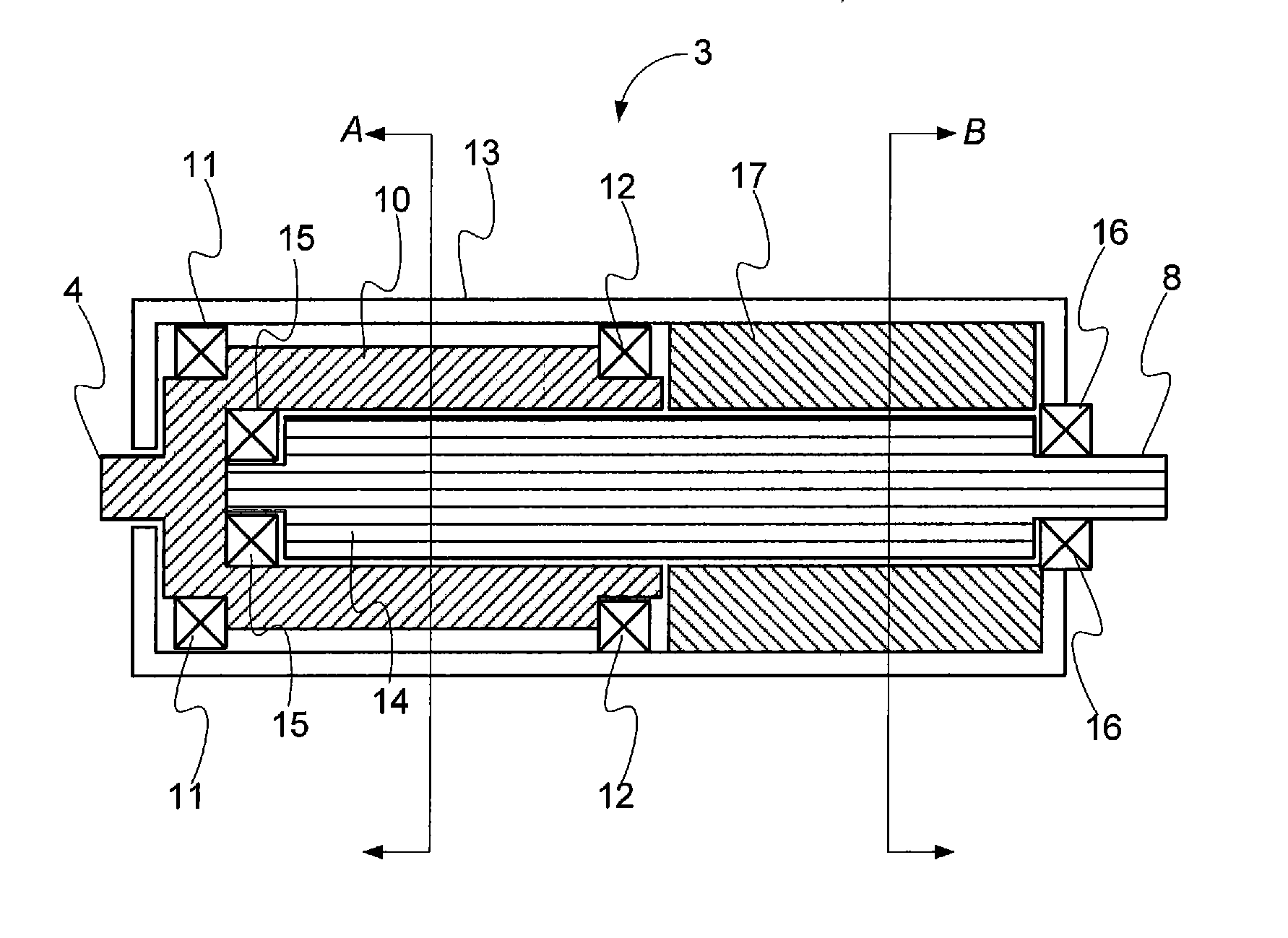
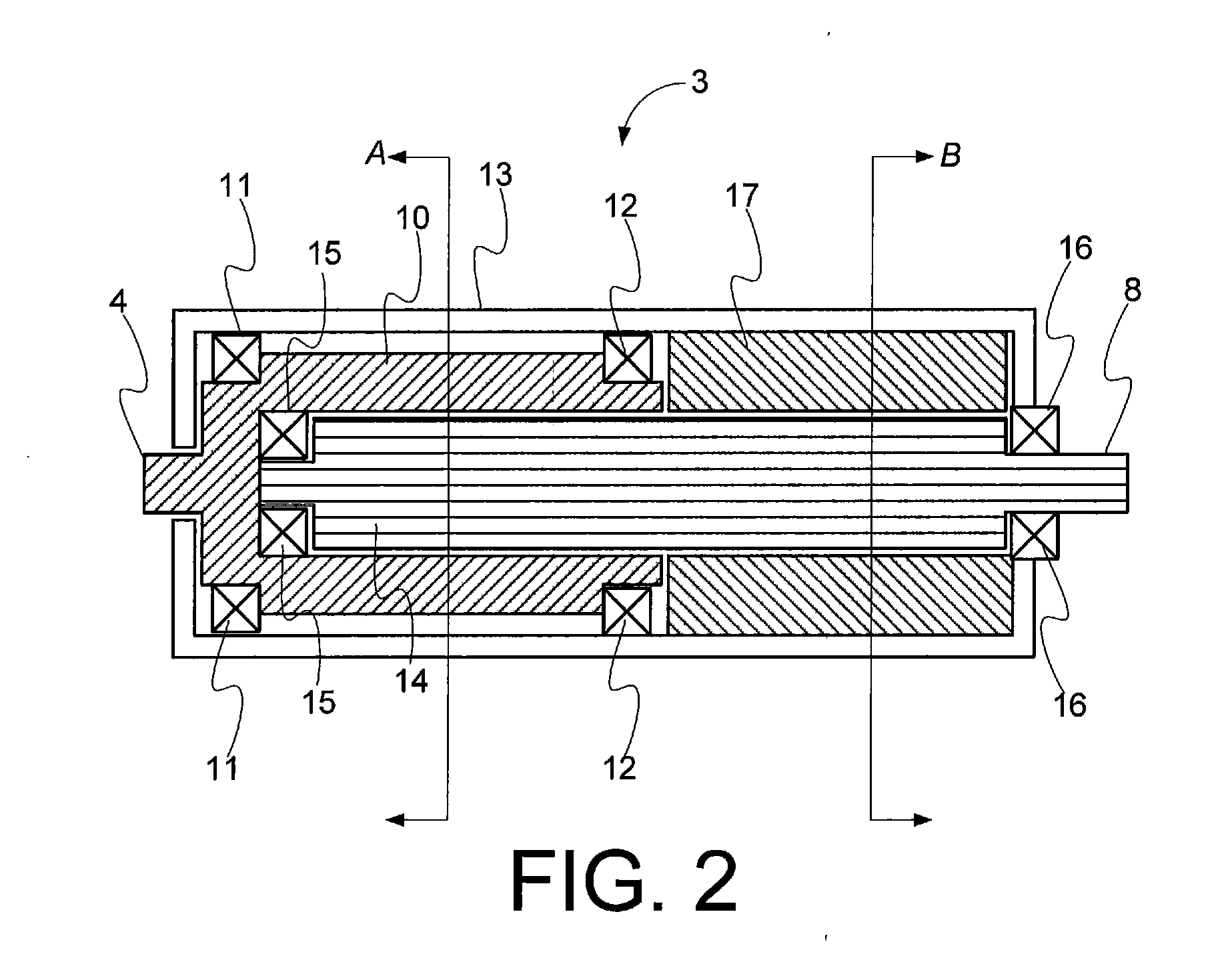
[0015]The present disclosure provides a system and method for providing a hybrid power train for a machine. The hybrid power train utilizes a dual rotor electric machine to convert rotational engine energy into a rotational output with no direct mechanical connection between the engine and the output. In an embodiment, the dual rotor electric machine employs a first rotor and a stator, stacked axially. A second rotor is stacked radially within the first rotor and the stator, such that rotation of the first rotor induces currents in the second rotor, and the induced currents then interact with the stator to produce a torque in the second rotor.

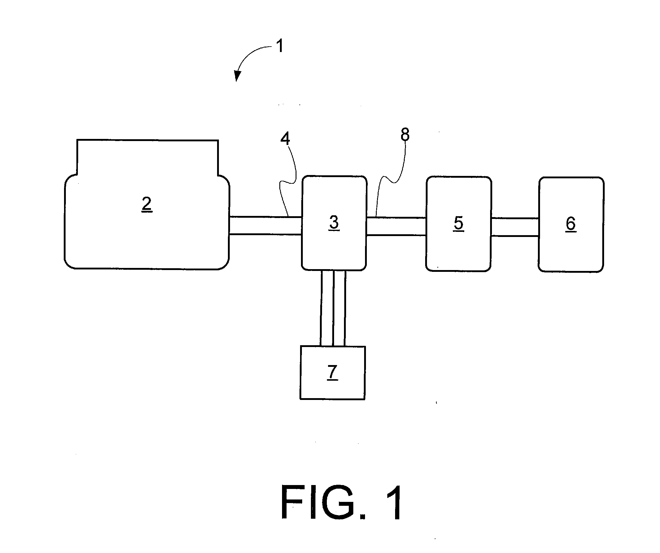
[0016]Turning to the figures, FIG. 1 is a schematic overview diagram of a hybrid drive system in accordance with an embodiment of the disclosure. The illustrated hybrid drive system 1 includes an internal combustion engine 2 coupled to a dual rotor electric machine 3. The input 4 of the dual rotor electric machine is coupled to the internal com...


PUM


Abstract

A series electric drive includes a cylindrical first rotor with a number of permanent magnets therein and an input linked to the cylindrical first rotor. The series electric drive further includes a cylindrical second rotor stacked radially within the cylindrical first rotor, the cylindrical second rotor being a wound rotor, and an output being linked to the cylindrical second rotor. A cylindrical stator is stacked axially relative to the first rotor, and a portion of the second rotor is stacked radially within the cylindrical stator, the cylindrical stator being a wound stator.

Description

TECHNICAL FIELD OF THE DISCLOSURE[0001]The present disclosure relates to electric drive for machines and, more particularly, relates to a system and method for providing a dual rotor electric drive in a hybrid machine.BACKGROUND OF THE DISCLOSURE[0002]During the use of machines powered by internal combustion engines, fuel is consumed and pollution may be generated roughly in proportion to the amount of fuel consumed. Moreover, depending upon whether the internal combustion engine is operated at its peak efficiency configuration, the use of internal combustion engines entails varying degrees of inefficiency in the conversion of fuel to power.[0003]One way to reduce the fuel usage and increase the efficiency of machines that utilize internal combustion engine power is to provide a hybrid drive system wherein the internal combustion engine provides power that is converted to electric power and used to electrically drive the machine. An example of this is U.S. Pat. No. 8,240,412 to Andr...

Claims


Application Information

Patent Timeline
Patent Type & Authority Applications(United States)
IPC IPC(8): B60K6/46H02K49/04B62D55/00H02K16/02
CPCB60K6/46B62D55/00Y10S903/903H02K49/043H02K16/02H02K51/00H02K16/025B60K6/26B60K6/448B60K2006/262B60K2006/266H02K99/00Y02T10/62
Inventor RAMAMOORTHY, KRISHNAKUMARALKHOULI, SAMI
Owner CATERPILLAR INC
Features
  • R&D
  • Intellectual Property
  • Life Sciences
  • Materials
  • Tech Scout
  • Unparalleled Data Quality
  • Higher Quality Content
  • 60% Fewer Hallucinations
Learn More