Coated rotary tool
a rotary tool and tool technology, applied in the direction of superimposed coating process, soldering apparatus, auxillary welding devices, etc., can solve the problems of remarkably short tool life, high temperature of friction stir welding tool, low cost required to join aluminum alloys, etc., to achieve excellent heat insulation properties, excellent oxidation resistance and wear resistance, and short time
- Summary
- Abstract
- Description
- Claims
- Application Information
AI Technical Summary
Benefits of technology
Problems solved by technology
Method used
Image
Examples
example 1
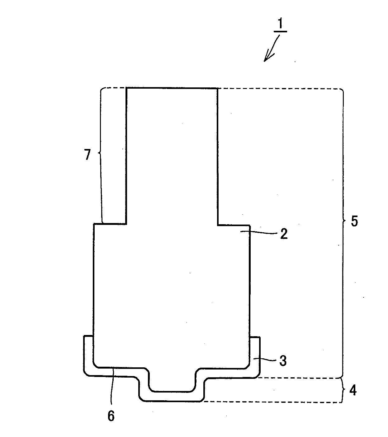
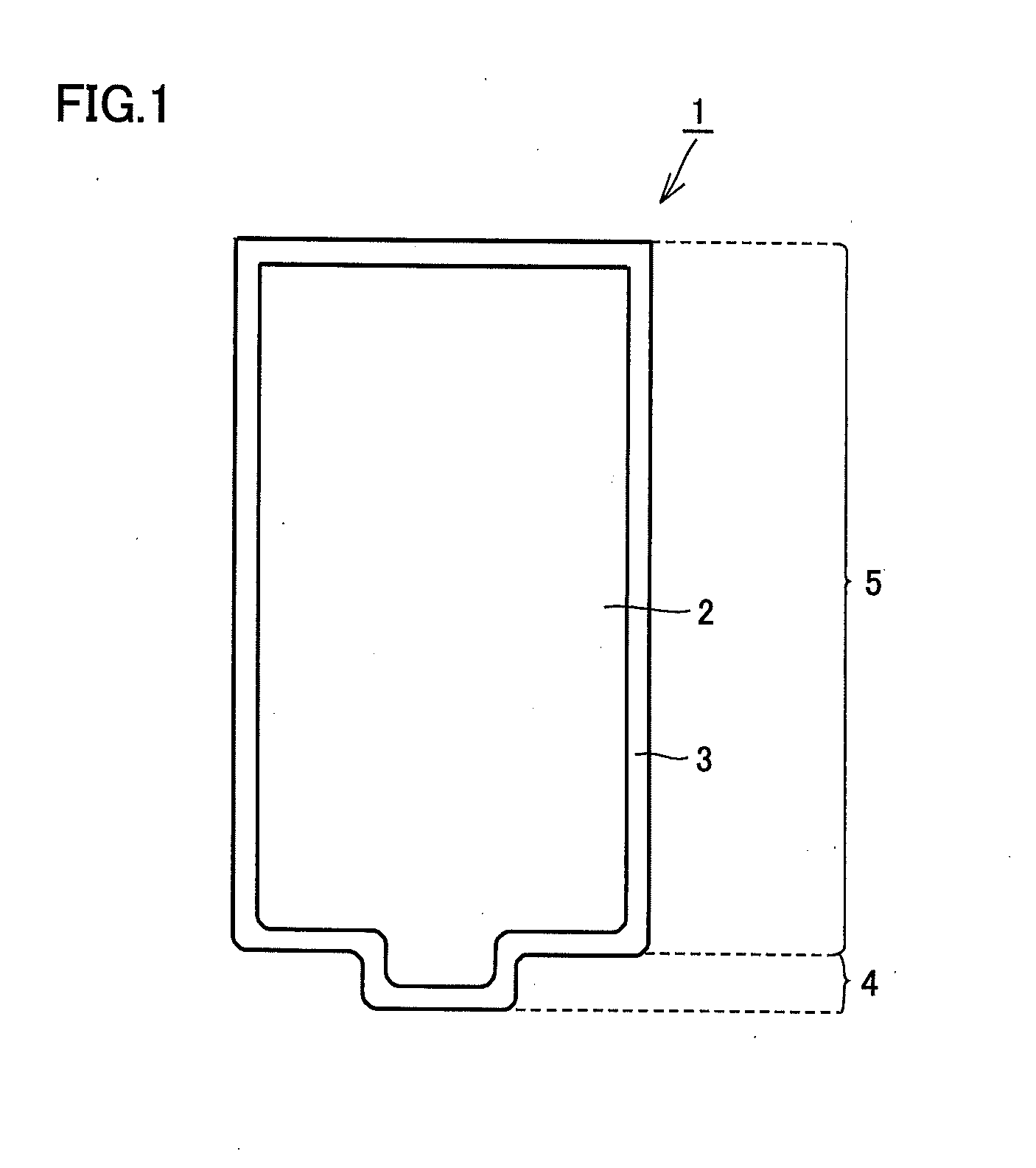
[0064]In the present example, the tool for friction stir welding shown in FIG. 1 is fabricated. The tool for friction stir welding in the present example has cylindrical portion 5 having a substantially cylindrical shape whose diameter is 10 mm and whose height is 20 mm, and probe portion 4 protruding concentrically with cylindrical portion 5 at a central portion of the tip of cylindrical portion 5. Probe portion 4 has a substantially cylindrical shape whose diameter is 4 mm and whose height is 0.7 mm.
Fabrication of Tool for Friction Stir Welding
[0065]First, a base material having the above-mentioned tool shape and made of a material shown in Table 1 below is prepared as the base material of the tool for friction stir welding. This base material is made of cemented carbide and includes WC crystal grains, and the average particle size of each of these crystal grains (in the surface of the base material (interface portion with the coating layer)) is as shown in Table 1.
TABLE 1evaluat...
examples 2 to 7 and 9
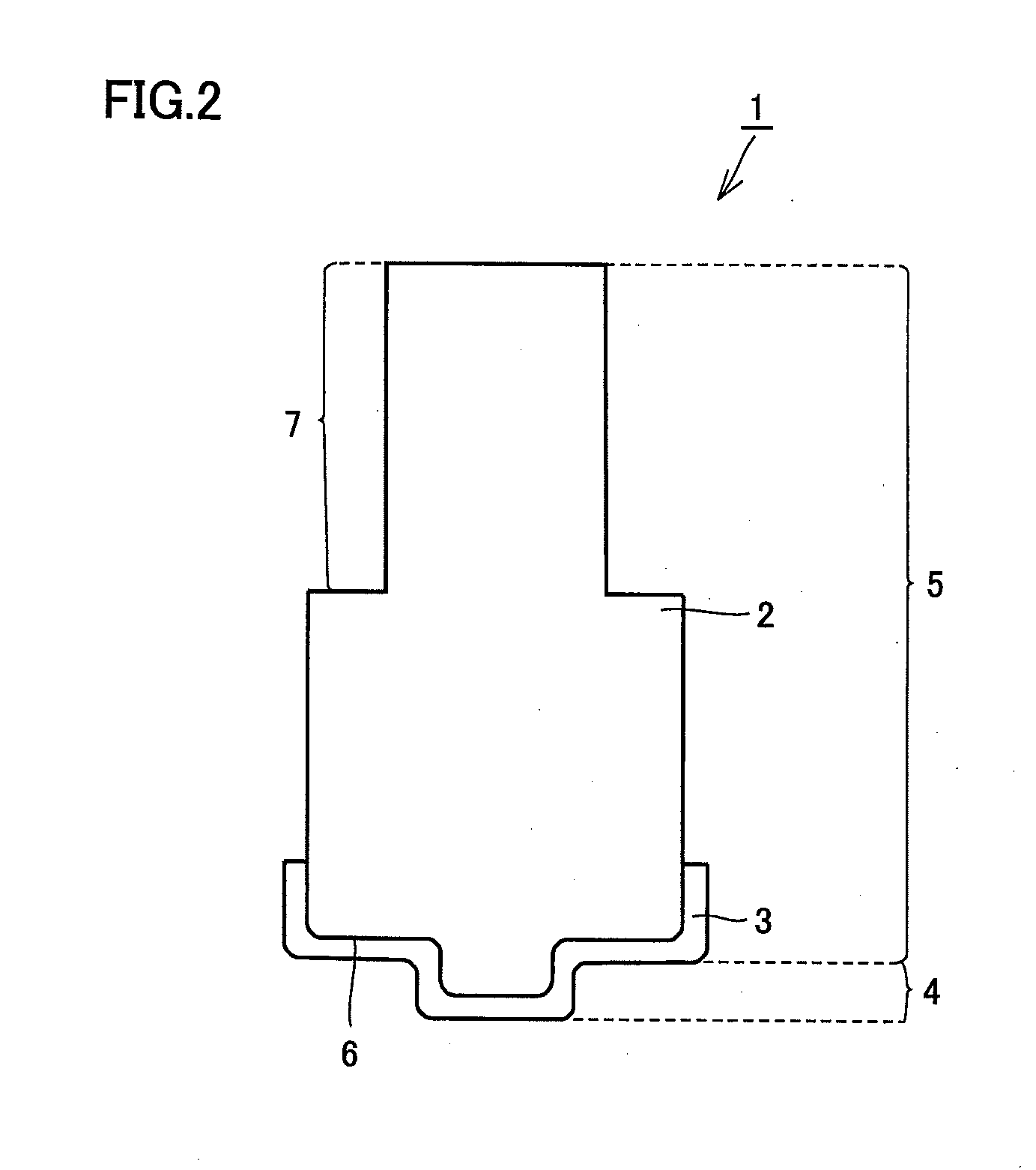
[0069]In each of Examples 2 to 7 and 9, a tool for friction stir welding is fabricated using a method similar to that in Example 1 except that the configuration and composition of the coating layer are different from those in Example 1 as shown in Table 2 below. For example, in Example 3, 120 layers of a Ti0.5Al0.5N layer having a thickness of 0.05 μm and 120 layers of a Al0.75Ti0.25N layer having a thickness of 0.05 μm are alternately stacked on the base material, and thereby the coating layer formed of 240 layers in total is formed. When two types of compositions are listed in the section “composition” of coating layer in Table 2, it means that a layer having a composition shown on the left side is formed, and thereafter, a layer having a composition shown on the right side is formed directly on the layer.
TABLE 2coating layercomposition and structure(* A number in the parenthesis beside anumberlayerthermalcomposition refers to a thickness (μm)ofthicknesspermeabilitycompressiveport...
example 8
[0070]In Example 8, a tool for friction stir welding is fabricated similarly to Example 3 except that the coating layer is formed not only on the probe portion and the shoulder portion but also on the chuck portion.
PUM
| Property | Measurement | Unit |
|---|---|---|
| melting point | aaaaa | aaaaa |
| temperature | aaaaa | aaaaa |
| temperature | aaaaa | aaaaa |
Abstract
Description
Claims
Application Information
 - R&D
- Intellectual Property
- Life Sciences
- Materials
- Tech Scout
- Unparalleled Data Quality
- Higher Quality Content
- 60% Fewer Hallucinations
Browse by: Latest US Patents, China's latest patents, Technical Efficacy Thesaurus, Application Domain, Technology Topic, Popular Technical Reports.
© 2025 PatSnap. All rights reserved.Legal|Privacy policy|Modern Slavery Act Transparency Statement|Sitemap|About US| Contact US: help@patsnap.com


