Sternal Retractor

a retractor and sternum technology, applied in the field of medical devices, can solve the problems of waste of all other blood components, inability to perform most cases, and inability to achieve the effect of reducing bleeding and reducing sternal breakag

Active Publication Date: 2014-05-08
EMORY UNIVERSITY
View PDF3 Cites 6 Cited by
  • Summary
  • Abstract
  • Description
  • Claims
  • Application Information

AI Technical Summary

Benefits of technology

[0009]In one aspect the present invention provides a device and method to reduce bleeding from a cut sternal edge during surgery performed via a sternotomy. In another aspect, the present invention provides a device and method to reduce sternal breakage during surgery performed via a sternotomy.
[0013]The present device and method for reducing the incidence of sternal fractures during surgical procedures performed via a sternotomy involves the use of sternal retractor blades which extend substantially the length of the sternum and distribute force across substantially the entire sternum during the sternotomy. Because the force applied to the cut sternum is more evenly distributed across the cut edge, the incidence of sternal fracture is reduced. In addition, the present device and method provide a means to create a trapezoidal opening of the sternal cavity, with a wider opening at the caudal end, which also reduces fractures.

Problems solved by technology

Recent reports in the literature have advocated discarding this shed blood, yet the sheer volume of blood shed from the sternal bone marrow makes this impractical in most cases.
Unfortunately, all other blood components (platelets, coagulation proteins, serum proteins, etc.) are wasted in this system and derangements in the normal clotting ability of the patient often result.
In either case, the volume of blood routinely shed from the sternum during cardiac surgery is a major cause of blood transfusion during and after cardiac surgery.
While these blades are currently available in different shapes and sizes to accommodate the numerous different available retractor systems, none are designed to reduce or prevent bleeding from the edges of the sternum.
Another issue with presently used sternal retractors is the issue of sternal fractures.
This applies a large amount of pressure against a relatively small surface area of the sternum, which leads to frequent fractures of the sternal edges.
These fractures contribute to increased sternal bleeding and are associated with delayed or incomplete healing and increased risk of sternal wound infection.

Method used


Image

  • Sternal Retractor
  • Sternal Retractor
  • Sternal Retractor

Examples


Embodiment Construction

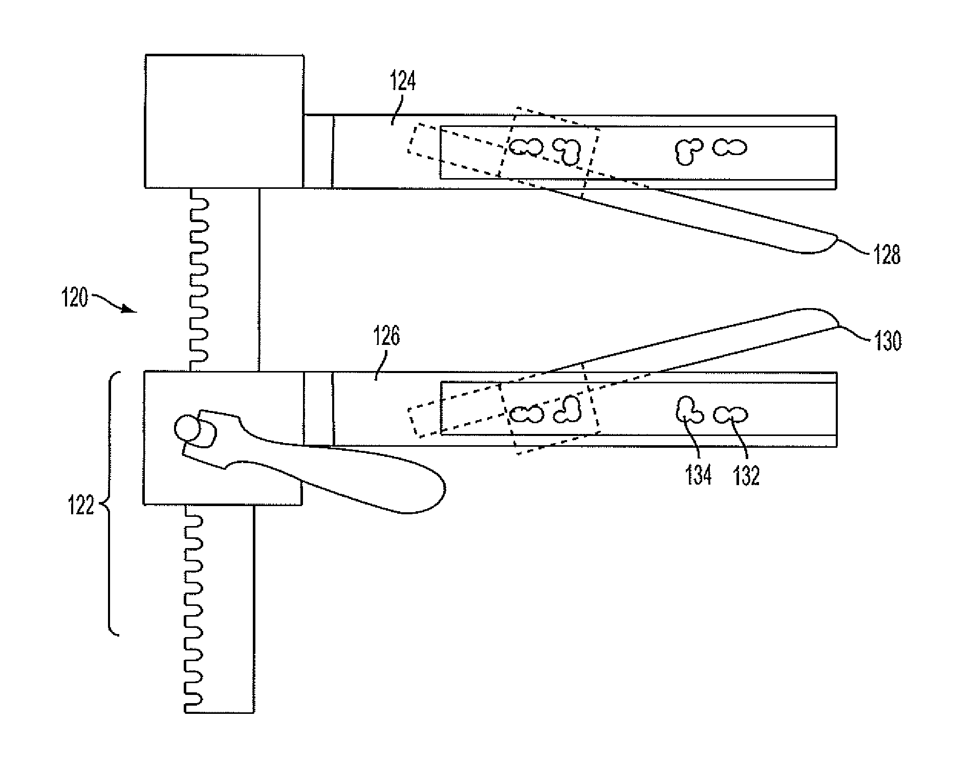
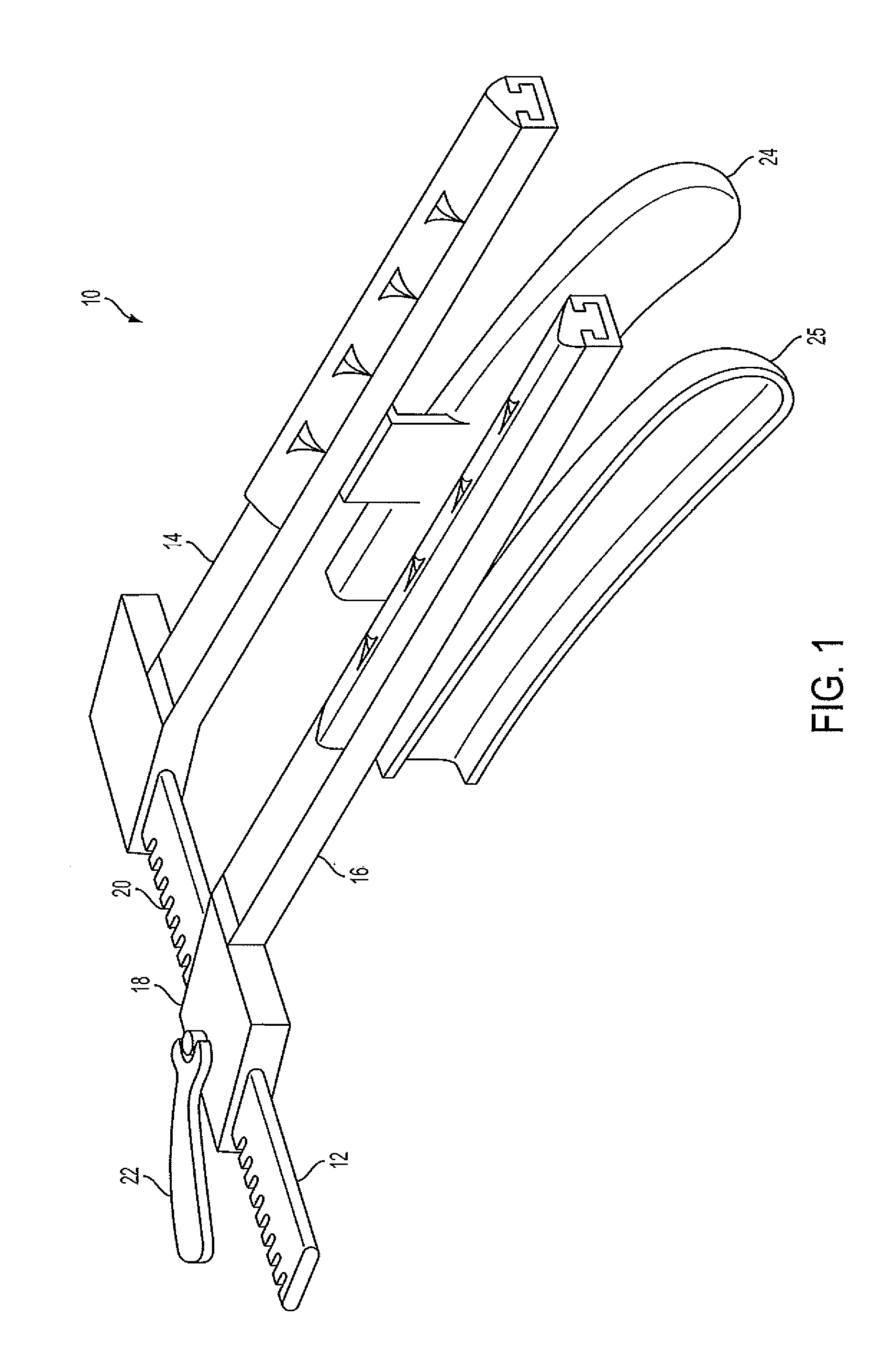
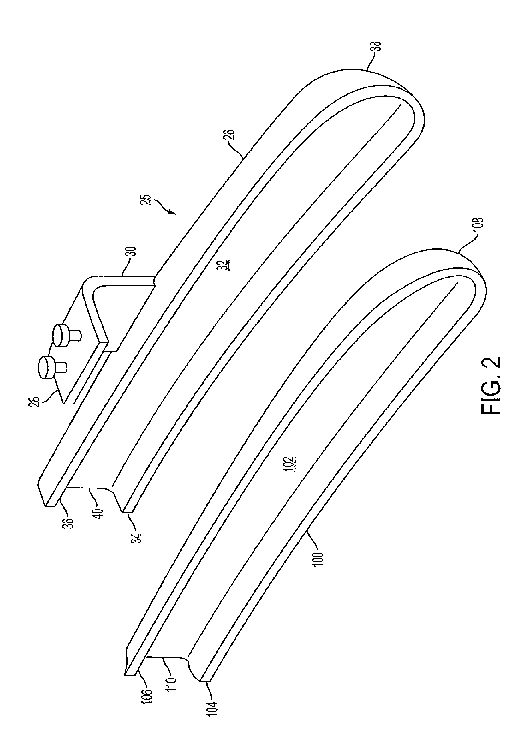
[0026]A typical sternal retractor has arms that attach to a rack, wherein one of the arms is fixed and the other is movable via a rack and pinion mechanism. Each arm carries a blade and the blades have sternal engaging surfaces facing away from each other. During a surgical procedure performed via a sternotomy, after the sternum is cut, the blades are inserted into the cut opening so that they rest against the sternal edges. The rack and pinion is engaged, causing the blades to move away from each other and causing the sternal edges to move away from each other. This is continued until a sternal opening is created that is large enough for the surgeon to access the inside of the chest.

[0027]The present invention is a sternal retractor that reduces bleeding from the cut edges of the sternum. The present invention also is a sternal retractor that reduces breakage or fracture of the sternum.

[0028]Note that while the present invention is described as relating to asternal retractor having...


PUM


Abstract

Devices and methods for sternal retraction that reduces bleeding from the cut edges of a sternum and reduces fracturing of the sternum during retraction. The devices and methods involve the use of sternal retractor blades having a certain geometry and inserts placed inside the sternal retractor blades during retraction of the sternotomy incision. The blades and inserts act to tamponade the blood flow from the cut sternal edge and reduce fracturing of the sternum during retraction.

Description

CROSS REFERENCE TO RELATED APPLICATIONS[0001]This application is related to U.S. application 61 / 609,662 filed on Mar. 12, 2012, and U.S. application Ser. No. 13 / 786,370 filed on Mar. 5, 2013, both of which are hereby incorporated by reference.BACKGROUND OF THE INVENTION[0002]The present invention relates generally to medical devices, and more specifically to a sternal retractor that minimizes blood loss and fractures of the sternum during use of the sternal retractor.[0003]Approximately 1,000,000 cardiac surgical procedures are performed worldwide each year. In the vast majority (>95%) of these procedures, access to the heart is achieved by dividing the sternum, a procedure known as a sternotomy. The sternum is the “breast bone”, a flat bone approximately 15 to 25 cm in length, 2 to 3 cm in width, and 8 to 16 mm in thickness. In fact, it consists of three bones connected by fused “joints”: the manubrium is 3 to 6 cm long and is located at the cephalad end, the sternum proper is 1...

Claims


Application Information

Patent Timeline
Patent Type & Authority Applications(United States)
IPC IPC(8): A61B17/02
CPCA61B17/0206A61B1/32
Inventor PUSKAS, JOHN D.HON, KELLY KLOSTERRIOS, ERICK ELADIOWONG-SHUI, BRIANMONEYPENNY, MARK JOSEPH
Owner EMORY UNIVERSITY
Why Eureka
Try Eureka