Embodiment 1
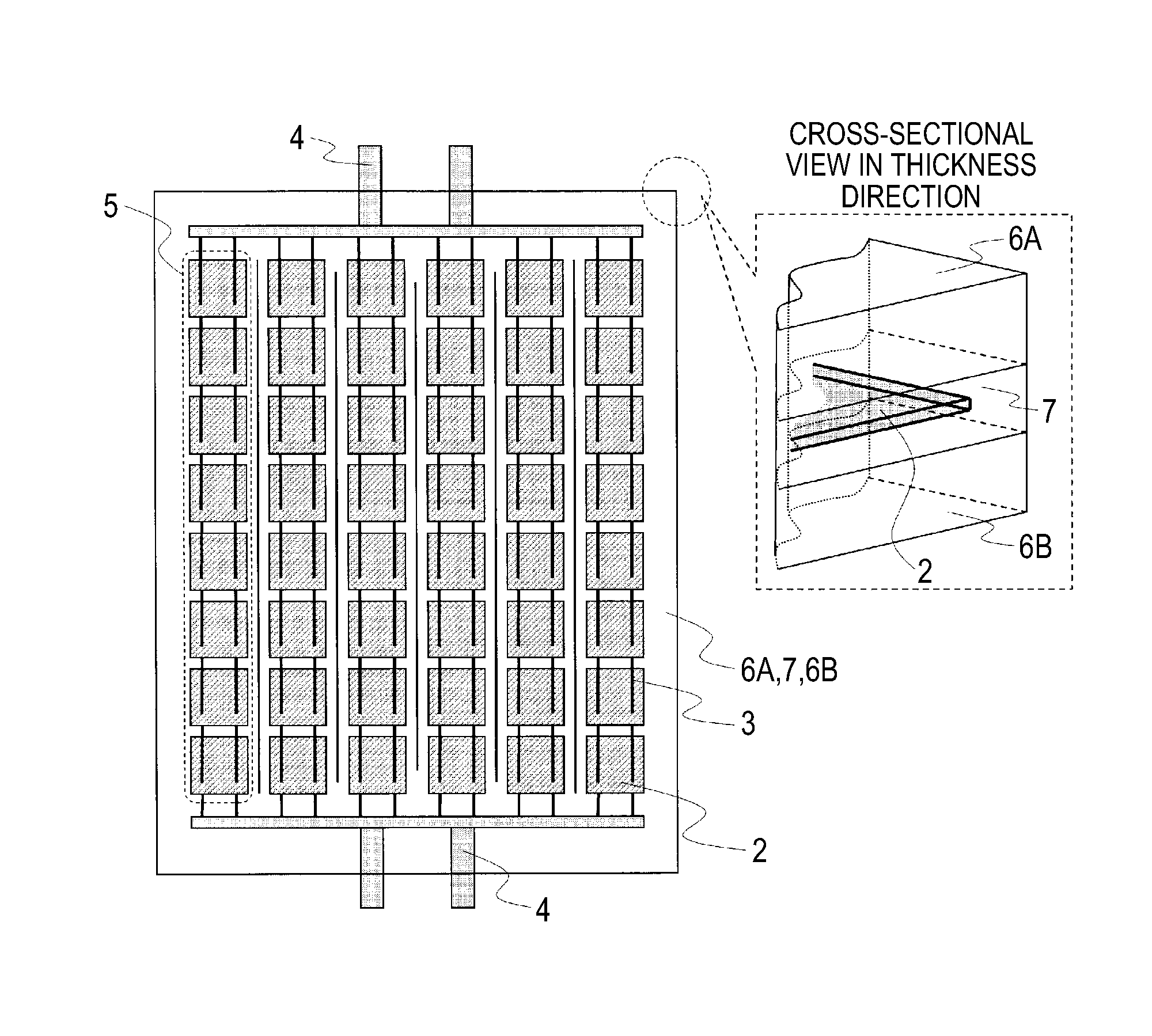
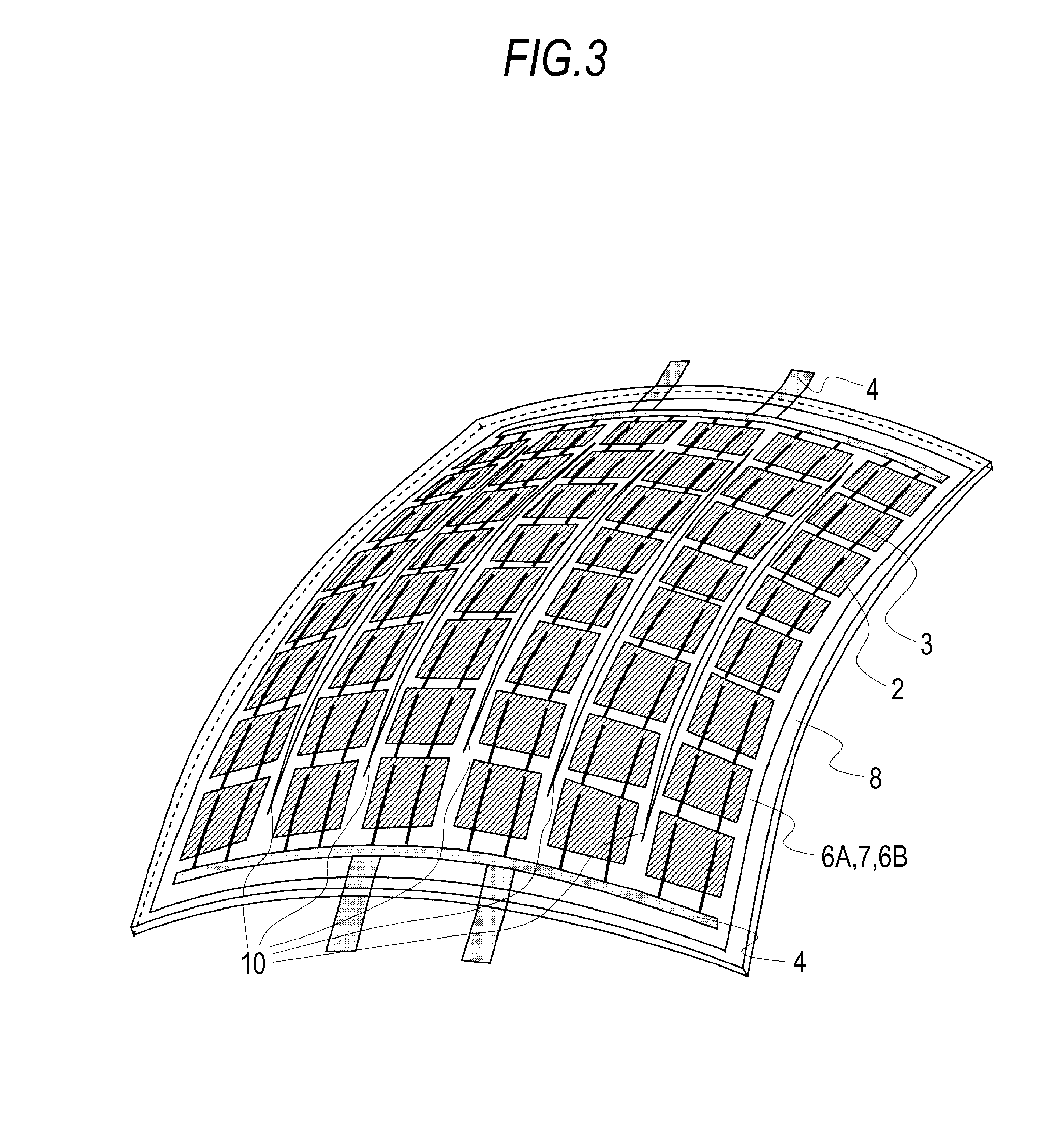
[0023]FIG. 1 is a view showing a solar cell sheet 1 included in a solar cell module shown in FIG. 3.
[0024]The solar cell sheet 1 according to the present embodiment includes at least plural solar cells 2, tabs between cells 3 electrically connecting adjacent solar cells 2 and a pair of transparent sheets (a front-face transparent sheet 6A and a rear-face sheet 6B sandwiching the cells 2 from both sides).
[0025]The solar cell sheet 1 usually requires, in addition to the above components, extraction electrodes 4 for electrically connecting both ends of solar cell strings 5 including plural solar cells 2 and extracting electric current to the outside of the solar cell sheet 1 and a filler resin 7 for filling in among the solar cells 2, the tabs between cells 3 and the extraction electrodes 4.
[0026]In the solar cell sheet 1, through incisions 10 piercing through the front-face transparent sheet 6A, the rear-face sheet 6B and the filler resin 7 are formed between strings of the solar cell strings 5 sealed with the front-face transparent sheet 6A, the rear-face sheet 6B and the filler resin 7 so as to pierce in a direction from the near side to the back side of FIG. 3. The plural through incisions 10 are formed in one direction and are provided along at least two or more solar cells 2 as shown in FIG. 3. The through incisions 10 are preferably provided so that the length thereof is gradually increased from the center toward both ends as shown in FIG. 3.
[0027]The front-face transparent sheet 6A and the rear-face sheet 6B are made of, for example, resin such as PET with flexibility. At least the front-face transparent sheet 6A is transparent, and in the case where the solar cells 2 to be used are solar cells supporting double-sided generation, it is preferable that the rear-face sheet 6B is also transparent. The tabs between cells 3 are metal wiring lines or made of a material having conductivity as well as flexibility such as conductive resin. Moreover, the filler resin 7 is a transparent material having rubber-like flexibility even after a sealing processing such as EVA (ethylene-vinyl acetate).
[0028]FIG. 2 shows a transparent curved surface substrate 8 included in the solar cell module of FIG. 3 according to Embodiment 1.
[0029]The transparent curved surface substrate 8 has a curved surface having a three-dimensional curvature as in a shape obtained by cutting out part of a spherical surface or an oval-sphere surface. Materials for the transparent curved surface substrate 8 maybe resin such as polycarbonate and glass as long as it is transparent.
[0030]FIG. 3 is the entire view of the solar cell module according to Embodiment 1.
[0031]FIG. 4A is a cross-sectional view showing from the extraction electrode 4 in the back side to the extraction electrode 4 in the near side in FIG. 3. A portion between the transparent curved surface substrate 8 and the solar cell sheet 1 under the substrate is filled with a fixing filler resin 9 to thereby bond the transparent curved surface substrate 8 and the solar cell sheet 1 to each other.
[0032]Here, the fixing filler resin 9 is assumed to be transparent.
[0033]FIG. 4B is a cross-sectional view showing from the left side to the right side of a central portion of the solar cell module of FIG. 3.
[0034]In FIG. 1 and FIG. 3, a vertical relationship and a stacking manner of members included in the solar cell sheet 1 and the solar cell module are complicated, and the transparent curved surface substrate 8, the fixing filler resin 9 and the front-face transparent sheet 6A are actually transparent and members arranged on the back side of these members can be seen through them, therefore, even when a certain member in the drawings is shown as positioned on the back side of another member, the outline shape thereof is not represented by a dashed line.
[0035]The vertical relationship and the staking manner of members included in the solar cell sheet 1 and the solar cell module in Embodiment 1 are shown in detail in FIG. 4A and FIG. 4B.
[0036]Next, purposes of forming the through incisions 10 in the solar cell sheet 1 will be explained.
[0037]When the solar cell sheet 1 is bonded and fixed to the transparent curved surface substrate 8 by the fixing filler resin 9, tensile stress occurs in the surface of the solar cell sheet 1 as the solar cell sheet 1 originally formed/sealed in the flat surface is bonded along the transparent curved surface substrate 8 having the three-dimensional curvature. As a result, the solar cell sheet 1 may be disfigured such that twists or wrinkles occur on the periphery of the sheet, or peeling from the transparent curved surface substrate 8 tends to occur from the generated twists or wrinkles on the solar cell sheet 1. As a result, disadvantages may arise also in functional aspects as the solar cell module.
[0038]In the present embodiment, the through incisions 10 provided between strings of the solar cell strings 5 of the solar cell sheet 1 slightly open, thereby alleviating the tensile stress in the surface occurring when the solar cell sheet 1 is bonded along the curved surface, which allows the solar cell sheet 1 to be bonded along the transparent curved surface substrate 8 without occurrence of twists or wrinkles on the sheet.
[0039]Additionally, the length of the through incisions 10 along the solar cell strings 5 is gradually increased as coming toward both ends as compared with the length of the through incision at the center of the solar cell sheet 1, thereby suppressing occurrence of twists or wrinkles of the sheet near the extraction electrodes 4.
[0040]In the direction from the extraction electrode 4 in the back side to the extraction electrode 4 in the near side in FIG. 3, bending occurring by bonding the sheet along the transparent curved surface substrate 8 is absorbed at portions between the solar cells 2 included in the solar cell strings 5 as shown in FIG. 4A. In a direction from the left side to the right side in the central portion of the solar cell module of FIG. 3, bending occurring by bonding the sheet along the transparent curved surface substrate 8 is absorbed by separating adjacent solar cell strings 5 from one another by the through incisions 10 as shown in FIG. 4B.
[0041]Moreover, a provisional solar cell module is once constructed in the state of the solar cell sheet 1 to be bonded to the transparent curved surface substrate 8, not bonding the solar cells 2 directly to the curved surface of the transparent curved surface substrate 8. According to the construction method, the solar cell sheet 1 can be fabricated by a well-known solar cell lamination technique, and reliability of the solar cell module can be assured in the same level as in the related art. Additionally, as the solar cell sheet 1 in which the solar cells 2 are arranged at predetermined positions is bonded to the transparent curved surface substrate 8, it is possible to easily fabricate the solar cell module with high quality in appearance as well as having the three-dimensional curved surface without requiring man-hours.
[0042]It is not always necessary to completely fill between the solar cell sheet 1 and the transparent curved surface substrate 8 with the fixing filler resin 9 as in the present Embodiment 1 as long as the solar cell sheet 1 can be fixed so as to be arranged along the transparent curved surface substrate 8 as well as light passing through the transparent curved surface substrate 8 from an upper surface side of the transparent curved surface substrate 8 and reaching a light-receiving generation surface of the solar cells 2 sealed in the solar cell sheet 1 is not completely blocked.
[0043]It is also preferable that a part between the solar cell sheet 1 and the transparent curved surface substrate 8 is filled. Furthermore, the solar cell sheet 1 and the transparent curved surface substrate 8 can be bonded and fixed to each other by double-faced tape and the like instead of using the fixing filler resin 9.