Machine or device monitoring and alert method and system

a technology for monitoring and alerting devices, applied in the field of machine or device monitoring and alert methods and systems, can solve problems such as troublesome problems, individual loses track of the operation cycle of the appliance, and the appliance goes unused for long periods of time, and achieves the effect of improving accuracy

Inactive Publication Date: 2014-05-15
LILL THOMAS MARTIN +1
View PDF0 Cites 42 Cited by
  • Summary
  • Abstract
  • Description
  • Claims
  • Application Information

AI Technical Summary

Benefits of technology

[0007]The present invention relates to methods and devices for monitoring appliances, machines, or devices and indicating when a change of state occurs. In one configuration, the features of the present invention are predicated upon new methods and devices for monitoring a change of state of appliances, machines, or devices. In another configuration, the features of the present invention are predicated upon new methods and devices for analyzing and conditioning signals generated by change of state monitors to provide improved accuracy. In still another configuration, the features of the present invention are predicated upon new methods and devices for eliminating false readings. Other advantageous features exist as shown and described herein.

Problems solved by technology

However, while these appliances are particularly helpful in performing tasks, once operation begins the individual often loses track of the operation cycle of the appliance and the appliance goes unused for lengthy periods of time with the clothes still inside.
With respect to dryers, this can a particularly troublesome problem for clothes that require hanging, after drying, to avoid wrinkling.
With respect to washing machines, wet clothes left in a washing machine over a prolonged period of time, particularly in tropical conditions, are susceptible to souring, mold, and mildew.
This can also be a problem for the user of a washer or dryer, when he or she is relying upon knowing when the washer or dryer has completed its cycle, in order to almost immediately use the clothes contained within the appliance for an appointment or other occasion.
However, these devices are typically complex in design, costly, require specially trained technician for installation, are impractical, or are just simply inoperable.
However, typically, alterations to appliances void any warrantee that the appliance may have.
Also, these systems do not work on all appliances and often generate false completion signals as a result of short interruptions between operation cycle segments.
However, again, during interruption between cycle segments the lack of current, or low current, creates a false completion signal.
However, many new appliances have variable operation time based upon operation necessities.
However, it has been discovered that these systems appear inoperable for lack of power, false completion readings, and simply lack enablement.
For example, it appears that these devices lack sufficient electrical power for monitoring operation cycle and generating wireless signals, without somehow electrically connecting the device to an AC supply.
Also, as often appliances are inadvertently banged, or knocked by other individuals or other appliances, these systems would appear to generate false operation signals.
More so, they are not capable of working on new ‘quiet’ appliances, such as ‘quiet washers’ and ‘quiet dryers’, which operate with substantially lower vibration and noise.
Finally, such systems do not appear to be in production and do not provide means for overcoming the aforementioned and other inherent problems.

Method used


Image

  • Machine or device monitoring and alert method and system
  • Machine or device monitoring and alert method and system
  • Machine or device monitoring and alert method and system

Examples


second embodiment

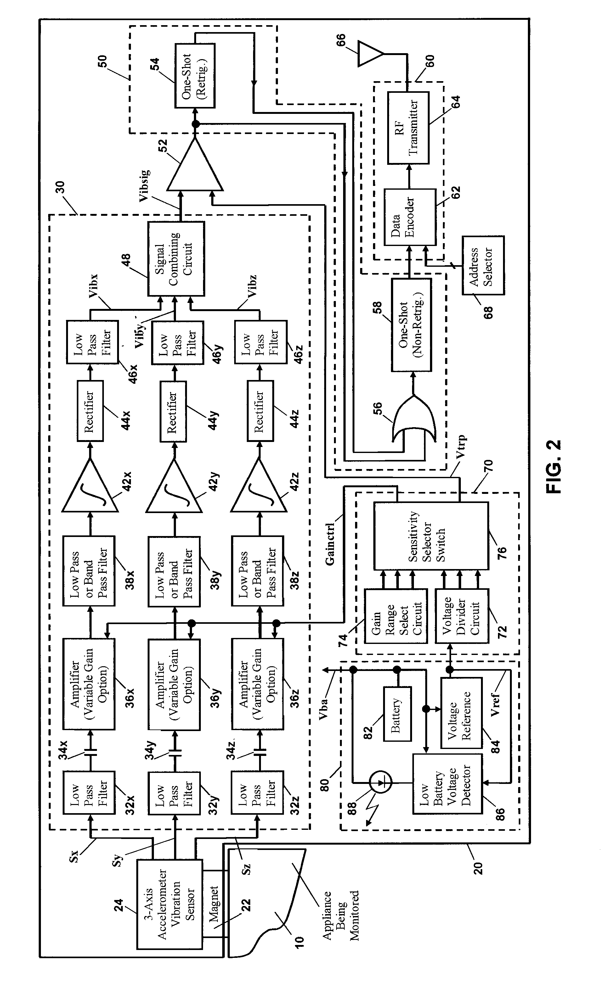
[0049]Combining Circuit 48 does not saturate for reasonable values of Vibx, Viby, and Vibz. In the invention, Signal Combining Circuit 48 derives the output “Vibsig” according to the following equation (often called the “square root of the sum of the squares” equation):

Vibsig=K2*]{square root over ([(Vibx)+(Viby)2+(Vibz)2)}{square root over ([(Vibx)+(Viby)2+(Vibz)2)}{square root over ([(Vibx)+(Viby)2+(Vibz)2)}]

K2, like K1, is a constant which is empirically derived such that “Vibsig” does not saturate for reasonable values of Vibx, Viby, and Vibz.

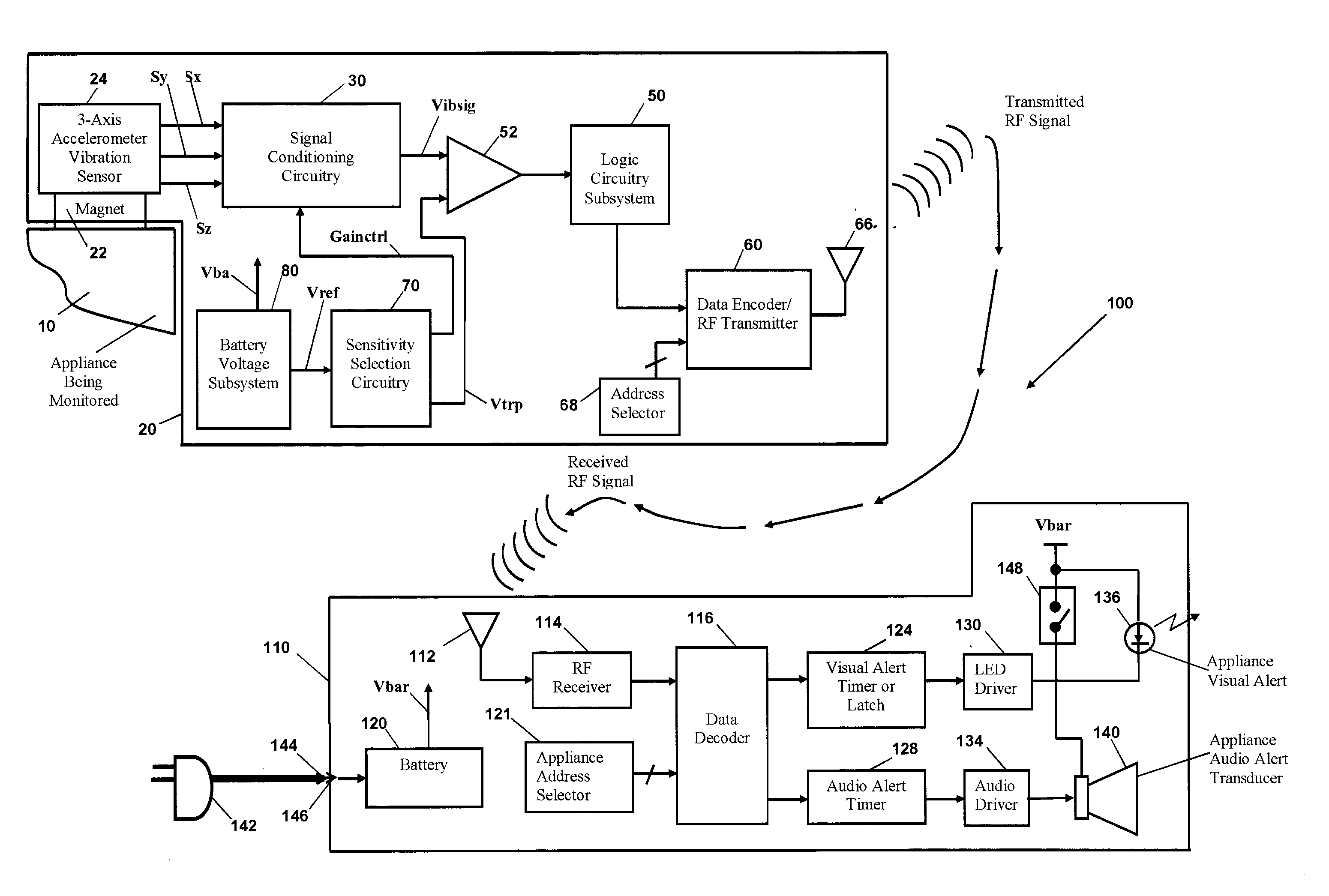
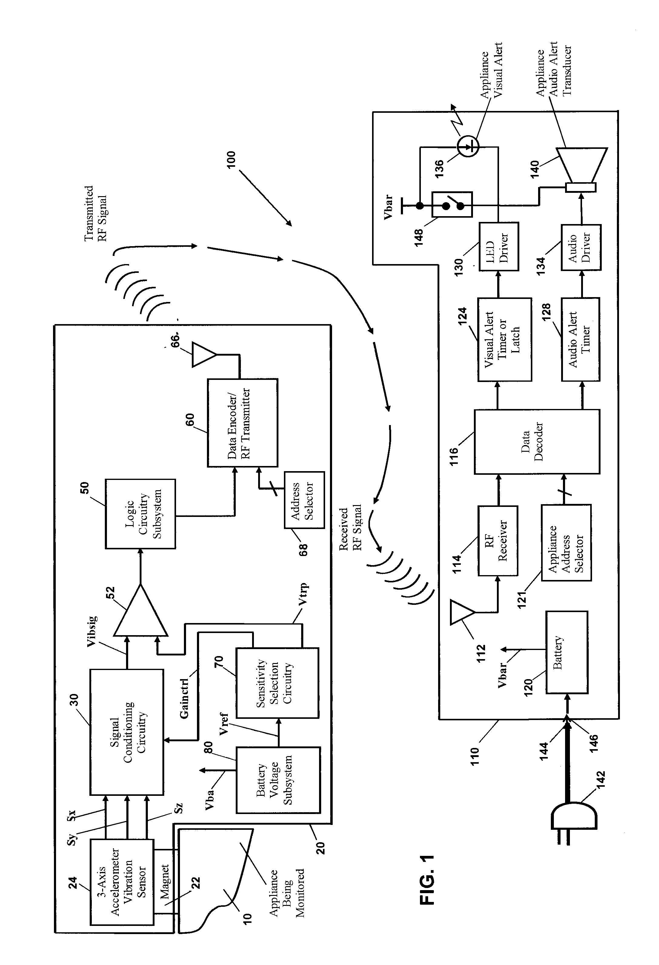
[0050]However it is derived by Signal Combining Circuit 48, “Vibsig” is sent to the positive input of Comparator 52. The purpose of Comparator 52 is to trip high when the amplitude of the appliance's vibration is above some predetermined value, which means the appliance is still in operation. Comparator 52 has a small amount of hysteresis, produced by using a small amount of positive feedback around the comparator, to reduce false triggerin...

case 1

[0090 is the simplest and cleanest case. It occurs when no temporary extraneous “On” / “Off” fluctuations occur while the Device Being Monitored 10 makes the transition from the “Off “state to the “On” state, and then from the “On” state to the “Off” state. Case 2 is the more complicated case. It occurs when temporary extraneous “On” / “Off” fluctuations do occur while the Device Being Monitored 10 makes the transition from the “Off “state to the “On” state, and then from the “On” state to the “Off” state.

[0091]We shall explain the oscillogram signals for Case 1, depicted in FIG. 16A, first. Please note that, for completeness, we may discuss the inputs and outputs of Inverter 213, OR Gate 214, and OR Gate 56, but these signals are not shown in the oscillograms of FIG. 16A. An explanation of how the Power-Up Transition State is detected for Case 1 follows. All the oscillograms start out at time t0, when the Device Being Monitored 10 is in the “Off” state and CompOut is low. As long as th...


PUM


Abstract

The present invention relates to methods and systems for monitoring of one or more machines or devices, such as washers and dryers, for a change of state and indicating when the change of state has occurred. In one aspect, the system comprises a monitor and alert unit which generates a signal indicative of the change of the state of the machine or device being monitored and a device or system to produce an alert notification based upon the signal. The monitor and alert unit includes an operational state sensor, a signal conditioner, and a comparator.

Description

CROSS-REFERENCE TO RELATED APPLICATIONS[0001]The present application is a continuation-in-part of U.S. non-provisional patent application Ser. No. 13 / 077,864, filed Mar. 31, 2011, which claims the benefit of U.S. Provisional Patent Application No. 61 / 341,586, filed Apr. 1, 2010, the contents of both being hereby incorporated by reference in their entirety for all purposes.FIELD OF THE INVENTION[0002]The present invention relates to methods and systems for monitoring of one or more machines or devices, such as washers, dryers, motors, pumps, and transformers for a change of state and indicating when the change of state has occurred.BACKGROUND[0003]Many households utilize appliances to perform mundane or time consuming tasks, which allows individuals to focus on other daily tasks requiring more attention. Such appliances include washing machines, dryers, dishwashers, microwaves, etc. However, while these appliances are particularly helpful in performing tasks, once operation begins th...

Claims


Application Information

Patent Timeline
Patent Type & Authority Applications(United States)
IPC IPC(8): G08B21/18
CPCG08B21/182G05B19/0428G07C3/00G05B2219/24099G05B2219/24102G05B2219/24107G05B2219/2642G05B2219/24012
Inventor LILL, THOMAS MARTINSHOEMAKER, RALPH
Owner LILL THOMAS MARTIN
Why Eureka
Try Eureka