Integrated Source Driver and Liquid Crystal Display Device Using the Same
- Summary
- Abstract
- Description
- Claims
- Application Information
AI Technical Summary
Benefits of technology
Problems solved by technology
Method used
Image

Examples
Embodiment Construction
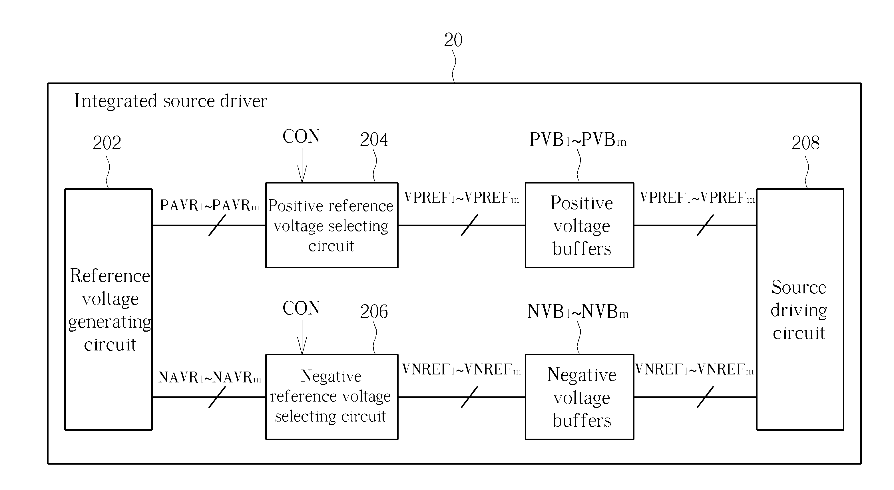
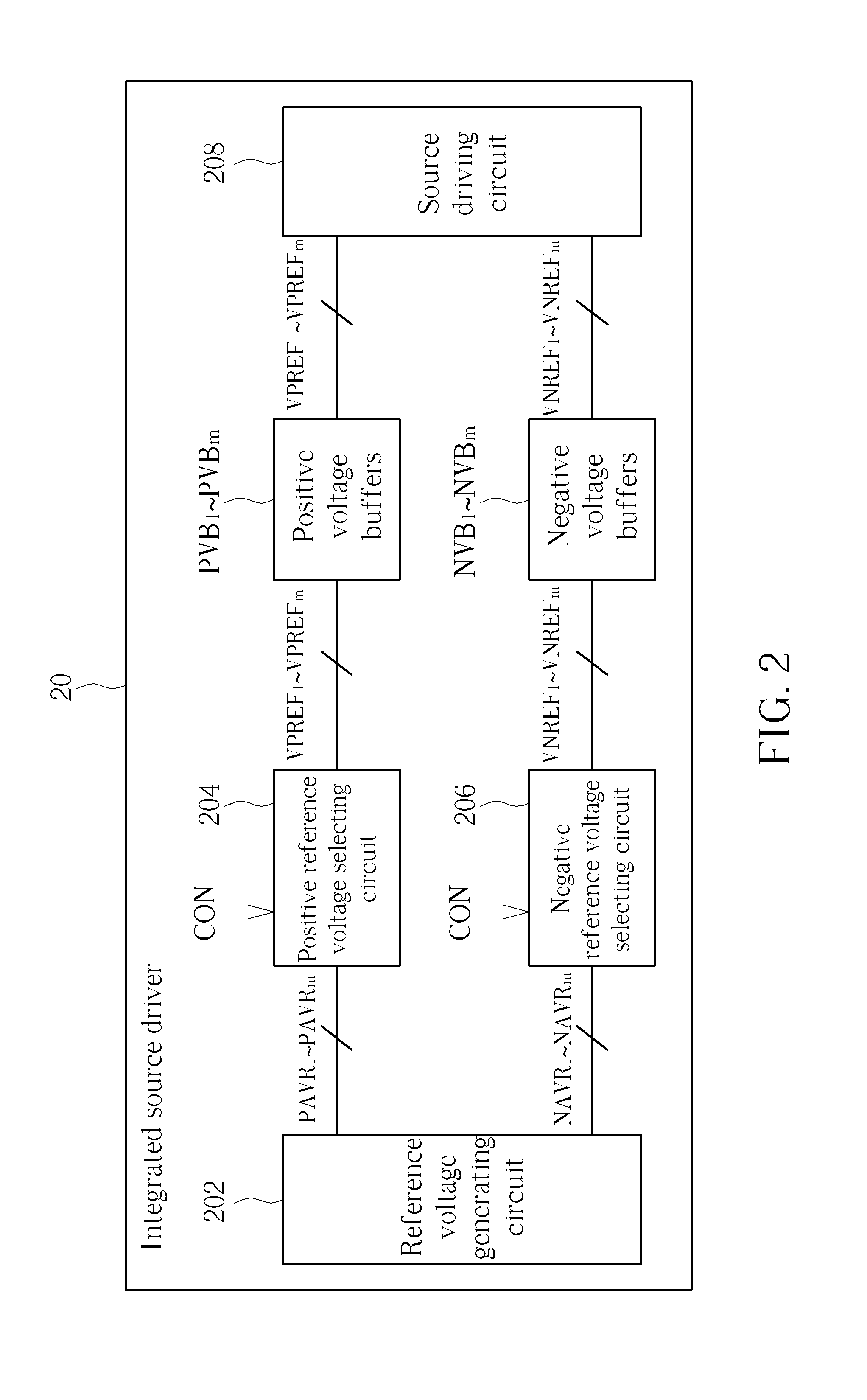
[0029]Please refer to FIG. 2, which is a schematic diagram of an integrated source driver 20 according to an embodiment of the present invention. As shown in FIG. 2, the integrated source driver 20 includes a reference voltage generating circuit 202, a positive reference voltage selecting circuit 204, a negative reference voltage selecting circuit 206, positive voltage buffers PVB1-PVBm, negative voltage buffers NVB1-NVBm and a source driving circuit 208.
[0030]In short, the reference voltage generating circuit 202 provides positive adjustable voltage ranges PAVR1-PAVRm and negative adjustable voltage ranges NAVR1-NAVRm within a supply voltage VS and a ground level GND for the reference voltage selecting circuit 204 and 206. The reference voltage selecting circuit 204 and 206 includes digital to analog converters (DACs) PDAC1-PDACm, NDAC1-NDACm (not shown in FIG. 2), for selecting and generating internal reference voltages VPREF1-VPREFm, VNREF1-VNREFm within the adjustable voltage ra...
PUM
 Abstract
Description
Claims
Application Information