Liquid jetting apparatus and piezoelectric actuator

a piezoelectric actuator and liquid jetting technology, applied in the direction of electrical equipment, piezoelectric/electrostrictive/magnetostrictive devices, printing, etc., can solve the problems of troublesome connection by wire bonding, inability to connect wires to lead electrodes, and eventually decline in conduction reliability, so as to improve conductive reliability, the effect of suppressing the permeation of outside wet (moisture) and improving conductive reliability

Active Publication Date: 2014-05-15
BROTHER KOGYO KK
View PDF7 Cites 35 Cited by
  • Summary
  • Abstract
  • Description
  • Claims
  • Application Information

AI Technical Summary

Benefits of technology

[0020]In the present teaching, the piezoelectric element is hermetically sealed by being covered with the cover body section of the cover member. With this, it is prevented that outside wet (moisture) enters the piezoelectric element to cause a shirt circuit and migration and that dust adheres to the piezoelectric element. Further, the cover member also functions as a reinforcing member for reinforcing the piezoelectric element. However, the electrode of the piezoelectric element is required to be electrically connected to the driving device disposed on the outside of the cover member. In the present teaching, the first wiring section connected to the electrode of the piezoelectric element is arranged on the surface of the channel structure in which the piezoelectric element is arranged, and the second wiring section connected to the driving device is formed in the cover member covering the piezoelectric element. Further, the cover member includes the wiring connection section which extends along the surface of the channel structure and the second wiring section extends to the surface, of the wiring connection section, facing the first wiring section. Then, in a case that the cover member is joined to the channel structure, the wiring connection section is joined to the surface of the channel structure by being pressed thereto, and the second wiring section on the side of the wiring connection section is electrically conductive with the first wiring section on the side of the channel structure. Accordingly, the cover member in which the second wiring section is formed is joined to the surface of the channel structure, and thereby making it possible to perform the electrical connection between the piezoelectric element and the driving device easily.
[0021]The cover body section of the cover member preferably has a thickness of not less than a certain thickness for suppressing permeation of outside wet (moisture). Meanwhile, it is preferable that the wiring connection section is formed thinly to be deformable depending on the surface shape of the channel structure at the time of the joining in order to improve conductive reliability between the first wiring section and the second wiring section. In view of this, the wiring connection section is formed to have a thickness thinner than that of the cover body section in the present teaching. Accordingly, the first wiring section can be electrically conductive with the second wiring section reliably.
[0022]According to the present teaching, by joining the cover member in which the second wiring section is formed to the surface of the channel structure, the piezoelectric element can be electrically connected to the driving device easily. Further, the wiring connection section of the cover member joined to the surface of the channel structure is formed to have a thickness thinner than that of the cover body section covering the piezoelectric element. Since the cover member has a thickness of not less than a certain thickness, permeation of outside wet (moisture) is suppressed. Meanwhile, since the wiring connection section is formed thinly, when the wiring connection section is joined to the surface of the channel structure, the wiring connection section can be deformed depending on the surface profile of the channel structure and the conductive reliability between the first wiring section and the second wiring section is improved.

Problems solved by technology

However, the connection by the wire bonding is actually troublesome.
Especially, in a case that the lead electrodes, which are drawn from many piezoelectric elements respectively, are disposed densely in association with the high density arrangement of the nozzles of the ink-jet head, it is not easy to connect the wires to the lead electrodes one by one and the reliability of conduction declines eventually.

Method used


Image

  • Liquid jetting apparatus and piezoelectric actuator
  • Liquid jetting apparatus and piezoelectric actuator
  • Liquid jetting apparatus and piezoelectric actuator

Examples


Embodiment Construction

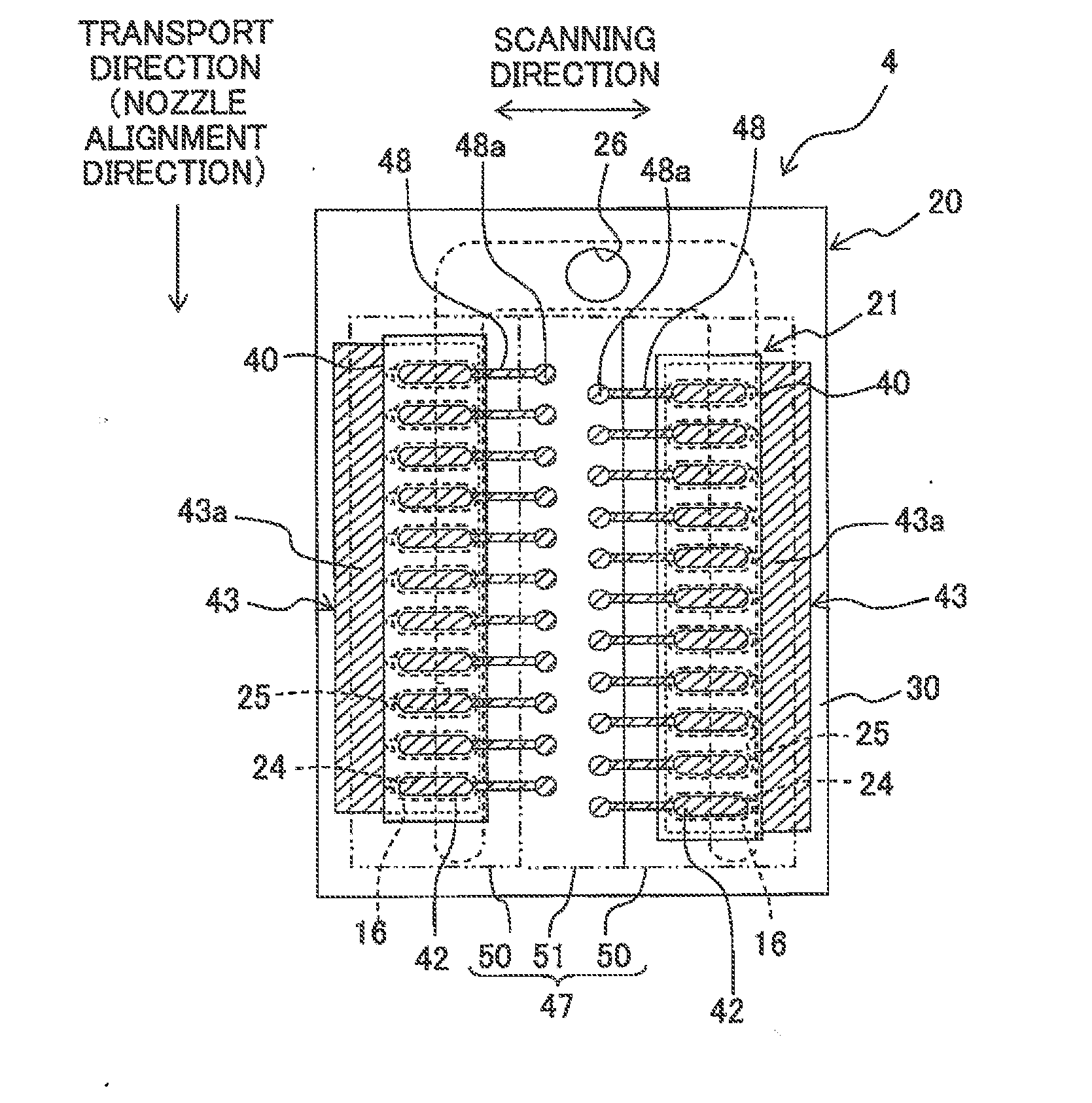
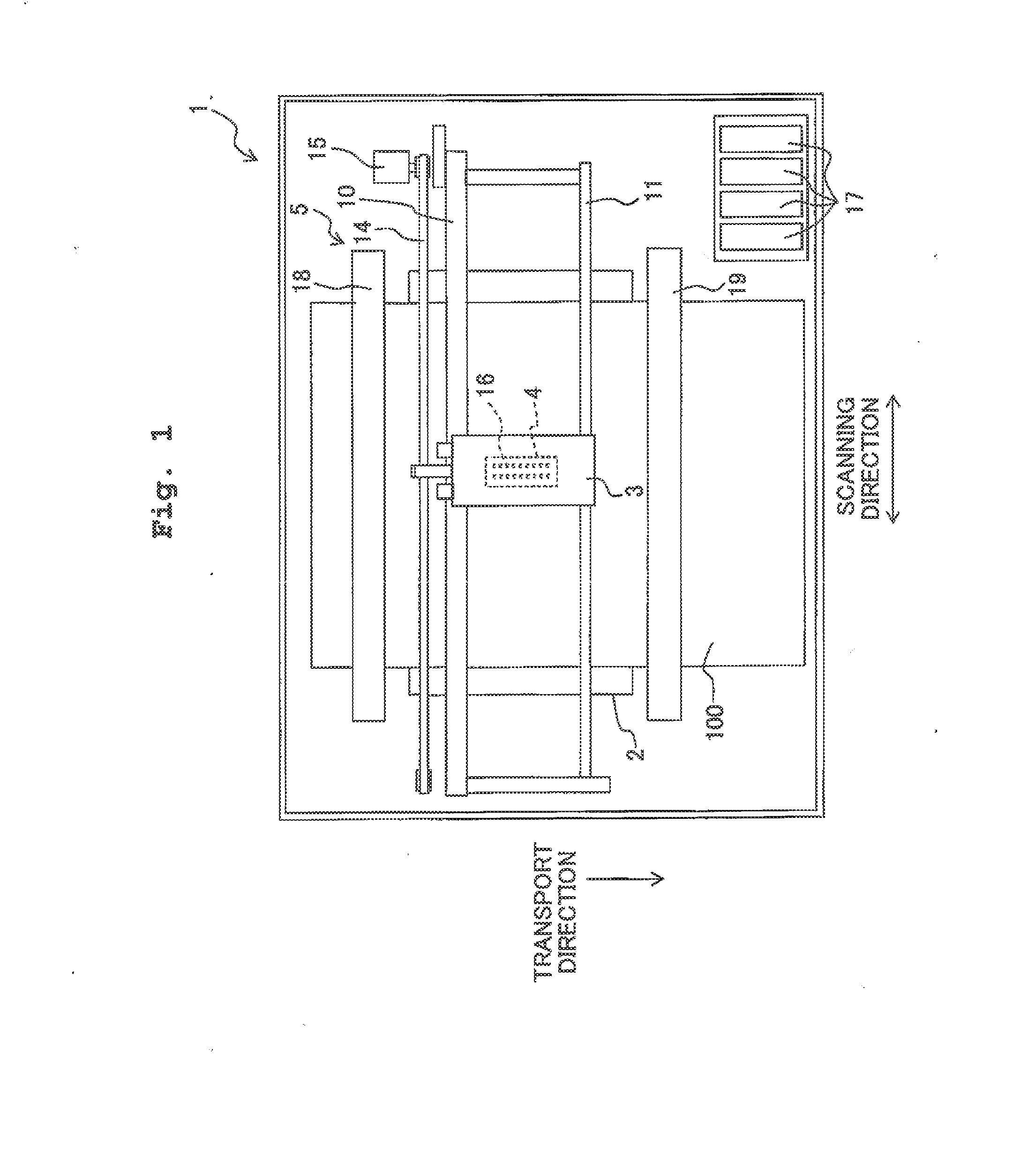
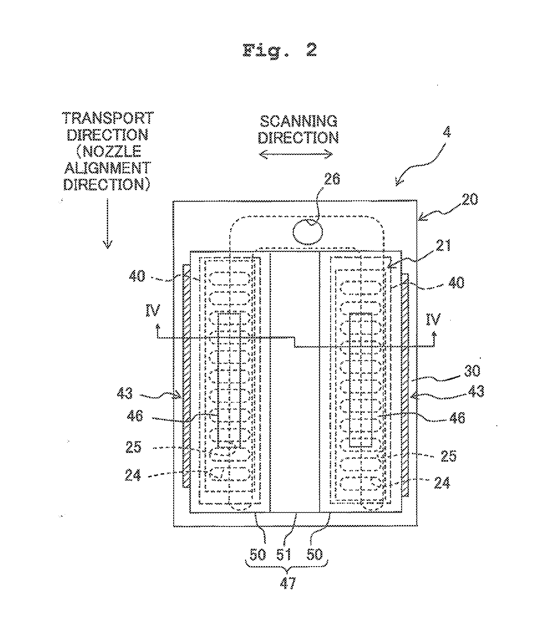
[0036]Next, an embodiment of the present teaching will be explained. Referring to FIG. 1, a schematic construction of an ink-jet printer 1 will be explained. Further, in the following explanation, the front side of the page of FIG. 1 is defined to be the upper side while the back side of the page is defined to be the lower side, and the explanation will be made by using the directional terms “upper” and “lower” as appropriate. As shown in FIG. 1, the ink jet printer 1 includes a platen 2, a carriage 3, an ink-jet head 4, a transport mechanism 5, etc.

[0037]A recording paper sheet 100, which is a recording medium, is placed on the upper surface of the platen 2. The carriage 3 is configured to be movable reciprocatingly in a scanning direction along two guide rails 10 and 11 in an area facing the platen 2. The carriage 3 is connected to an endless belt 14, and the endless belt 14 is driven by a carriage driving motor 15 to move the carriage 3 in the scanning direction.

[0038]The ink-jet...


PUM


Abstract

There is provided a liquid jetting apparatus, including: a channel structure in which a liquid channel including a nozzle and a pressure chamber communicating with the nozzle is formed; a piezoelectric element including a piezoelectric body and an electrode; a driving device; and a cover member joined to the surface of the channel structure. A first wiring section connected to the electrode is formed on the surface of the channel structure, and the cover member includes a cover body section and a wiring connection section. A second wiring section is formed in the cover member. The wiring connection section is joined to the surface of the channel structure in a state that the second wiring section is electrically conductive with the first wiring section. A thickness, of the wiring connection section is thinner than a thickness of the cover body section.

Description

CROSS REFERENCE TO RELATED APPLICATION[0001]The present application claims priority from Japanese Patent Application No. 2012-248073, filed on Nov. 12, 2012, the disclosure of which is incorporated herein by reference in its entirety.BACKGROUND OF THE INVENTION[0002]1. Field of the Invention[0003]The present invention relates to a liquid jetting apparatus and a piezoelectric actuator.[0004]2. Description of the Related Art[0005]There has been conventionally known a liquid jetting apparatus having a piezoelectric actuator which applies jetting energy to a liquid. For example, there has been known an ink-jet head including a channel forming substrate in which a plurality of pressure chambers, which are communicated with a plurality of nozzles respectively, are formed and a piezoelectric actuator provided in the channel forming substrate.[0006]One piezoelectric actuator includes a plurality of piezoelectric elements, which are arranged on the surface of an elastic film covering the pre...

Claims


Application Information

Patent Timeline
Patent Type & Authority Applications(United States)
IPC IPC(8): B41J2/14H01L41/047
CPCH01L41/0475B41J2/14201B41J2/14233B41J2002/14491H10N30/875H10N30/2047
Inventor KONDO, HIROFUMI
Owner BROTHER KOGYO KK
Why Eureka
Try Eureka