Fuel cell system and method for controlling fuel cell system

a fuel cell and system technology, applied in the field of fuel cell systems, can solve the problems of water build-up in the fuel cell, drop in etc., and achieve the effect of improving the output of the fuel cell and smooth draining water

Active Publication Date: 2014-05-15
TOYOTA JIDOSHA KK
View PDF0 Cites 15 Cited by
  • Summary
  • Abstract
  • Description
  • Claims
  • Application Information

AI Technical Summary

Benefits of technology

[0016]In a fuel cell actuated under cold environment, the present invention can provide a fuel cell system capable of improving an o

Problems solved by technology

), the generated water within the fuel cell freezes in a cold environment, e.g., below freezing temperature, whereas, the once frozen generated water is defrosted by heat generated at drive of the fuel cell and returns to water again, resulting in

Method used


Image

  • Fuel cell system and method for controlling fuel cell system
  • Fuel cell system and method for controlling fuel cell system
  • Fuel cell system and method for controlling fuel cell system

Examples


Embodiment Construction

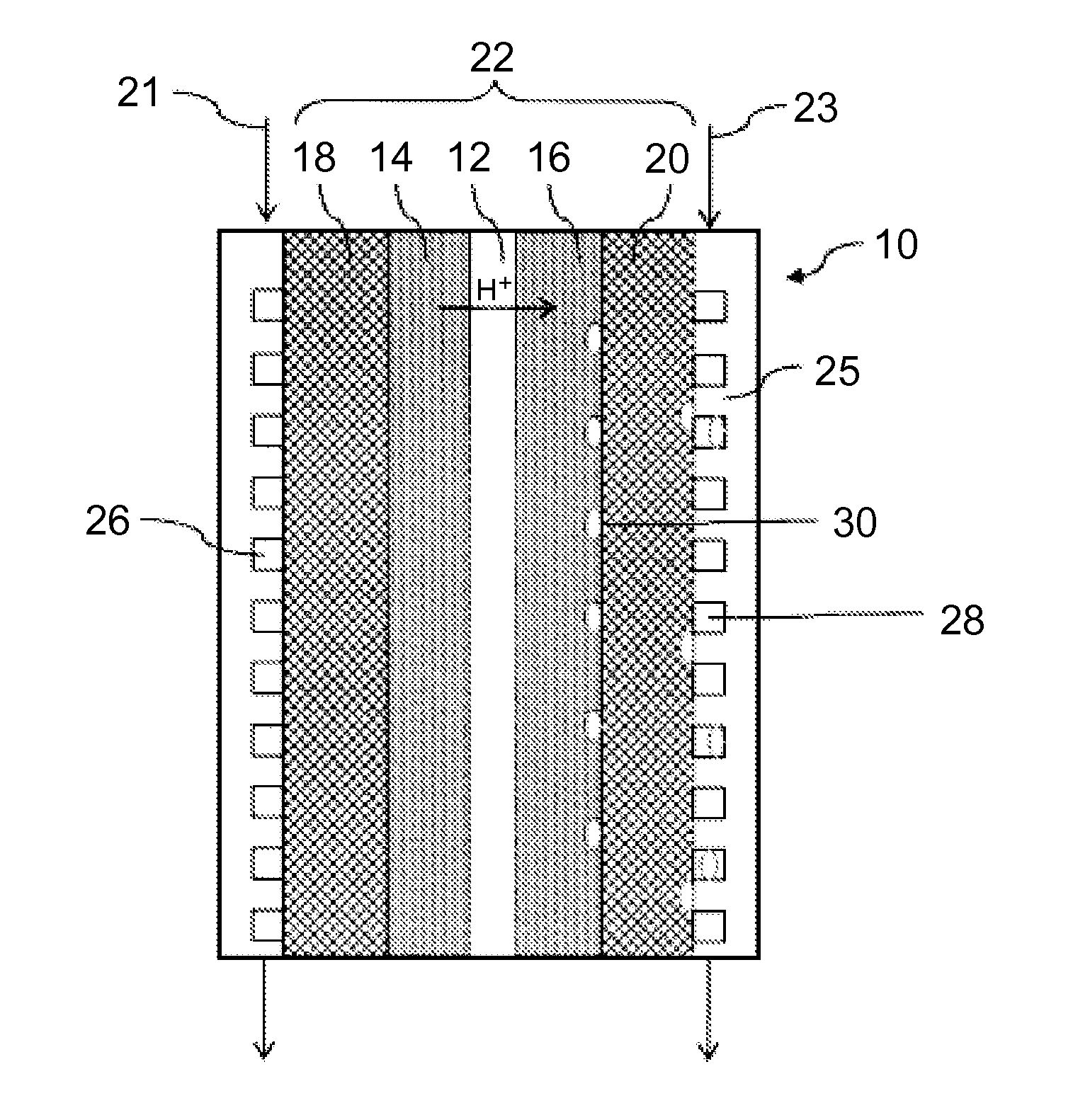
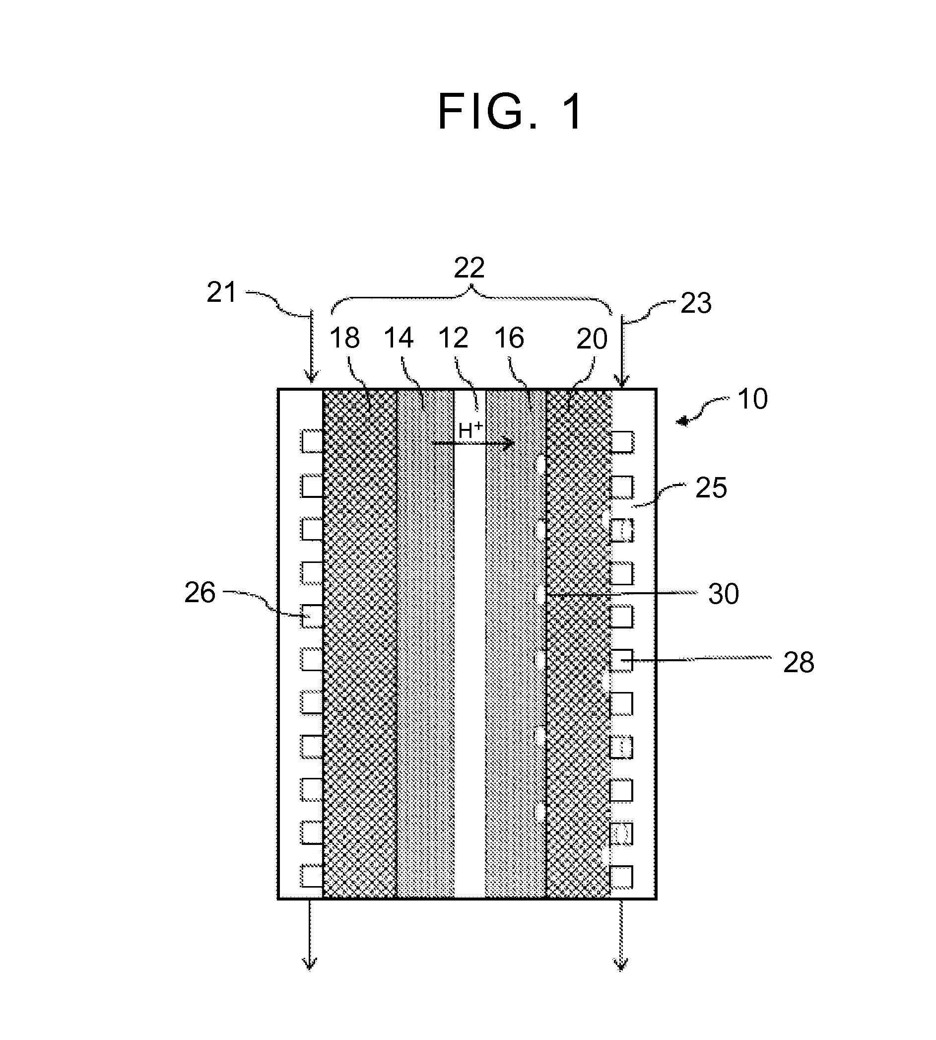
[0023]An exemplary embodiment of the present invention is described below with reference to FIGS. 1 through 3. FIG. 1 illustrates a fuel cell 10. The fuel cell 10 includes an electrolyte membrane 12, an anode catalyst layer 14, a cathode catalyst layer 16, an anode diffusion layer 18, and a cathode diffusion layer 20. The electrolyte membrane 12 includes an ion exchange membrane and has proton conductivity. The anode catalyst layer 14 and the cathode catalyst layer 16 are disposed respective sides of the electrolyte membrane 12. The anode diffusion layer 18 is disposed on the opposite side of the anode catalyst layer 14 from the electrolyte membrane 12 and the cathode diffusion layer 20 is disposed on the opposite side of the cathode catalyst layer 16 from the electrolyte 12. Accordingly, a membrane electrode assembly 22 is formed. Each side of the membrane electrode assembly 22 is provided with a separator 25 to form the fuel cell 10. A plurality of fuel cells 10 is layered to form...


PUM


Abstract

To improve an output of a fuel cell and power generation efficiency by enhancing drainage of the fuel cell upon actuation below freezing temperature. In a fuel cell system that generates power by supplying fuel gas and oxidant gas, the output of the fuel cell is measured when a temperature of the fuel cell after the actuation below freezing temperature exceeds 0 degree, and if a value of the output is equal to or less than a reference output value, pressure pulsation is applied to a cathode electrode to drain water built up in the fuel cell.

Description

TECHNICAL FIELD[0001]The Present invention relates to a fuel cell system including a fuel cell stack that is supplied with reactant gas to generate electricity and a method for controlling the fuel cell system.BACKGROUND ART[0002]A fuel cell includes a fuel cell stack made of a lamination body of a plurality of fuel cells (i.e., a plurality of single cells). Each of the plurality of single cells has a membrane-electrode assembly including an anode electrode on one surface of an electrolyte membrane and a cathode electrode on the other surface of the electrolyte membrane. The membrane-electrode assembly is sandwiched between a gas flow channel layer and a separator. The anode electrode is supplied with fuel gas containing hydrogen. The hydrogen is subjected to an oxidation reaction according to the following chemical formula (1) to thereby generate proton from the fuel gas. Thus generated proton travels to the cathode electrode through the electrolyte membrane. The cathode electrode ...

Claims


Application Information

Patent Timeline
IPC IPC(8): H01M8/04
CPCH01M8/04783H01M8/04104H01M8/04179H01M8/04253H01M8/0432H01M8/04395H01M8/04619H01M8/04753H01M2008/1095Y02E60/50H01M8/0438
Inventor ISHIKAWA, YUJI
Owner TOYOTA JIDOSHA KK
Why Eureka
Try Eureka