
Method and device for finishing a workpiece surface

Inactive Publication Date: 2014-05-15
SUPFINA GRIESHABER
View PDF11 Cites 7 Cited by
  • Summary
  • Abstract
  • Description
  • Claims
  • Application Information

AI Technical Summary

Benefits of technology

The present invention provides an improved method for machining workpieces which includes an additional movement perpendicular to the workpiece surface. The amplitude of this additional movement is important and should be between 0.2 mm and several millimeters in size. This method helps to achieve a high material removal rate while maintaining the integrity of the workpiece's macro geometry. Additionally, the workpiece surface and the active area of the finishing tool move relative to each other in a way that eliminates any relative movement parallel to the workpiece axis, resulting in a simpler and more efficient drive for the oscillatory movement of the finishing tool. In an alternative embodiment, the workpiece surface and the active area may move back and forth relative to each other in a way that combines the benefits of both oscillatory and rotary movements.

Problems solved by technology

It has been found that the aforedescribed hybrid technology is problematic in practice.
For example, the loads operating on the finishing tools are so high that the tools need to be replaced after a relatively short time.
Furthermore, a high noise level is produced, requiring complicated sound abatement measures.
Moreover, aerosols may be produced by nebulization of coolants or lubricants, which in the worst case may cause an explosion risk.

Method used


Image

  • Method and device for finishing a workpiece surface
  • Method and device for finishing a workpiece surface
  • Method and device for finishing a workpiece surface

Examples


Embodiment Construction

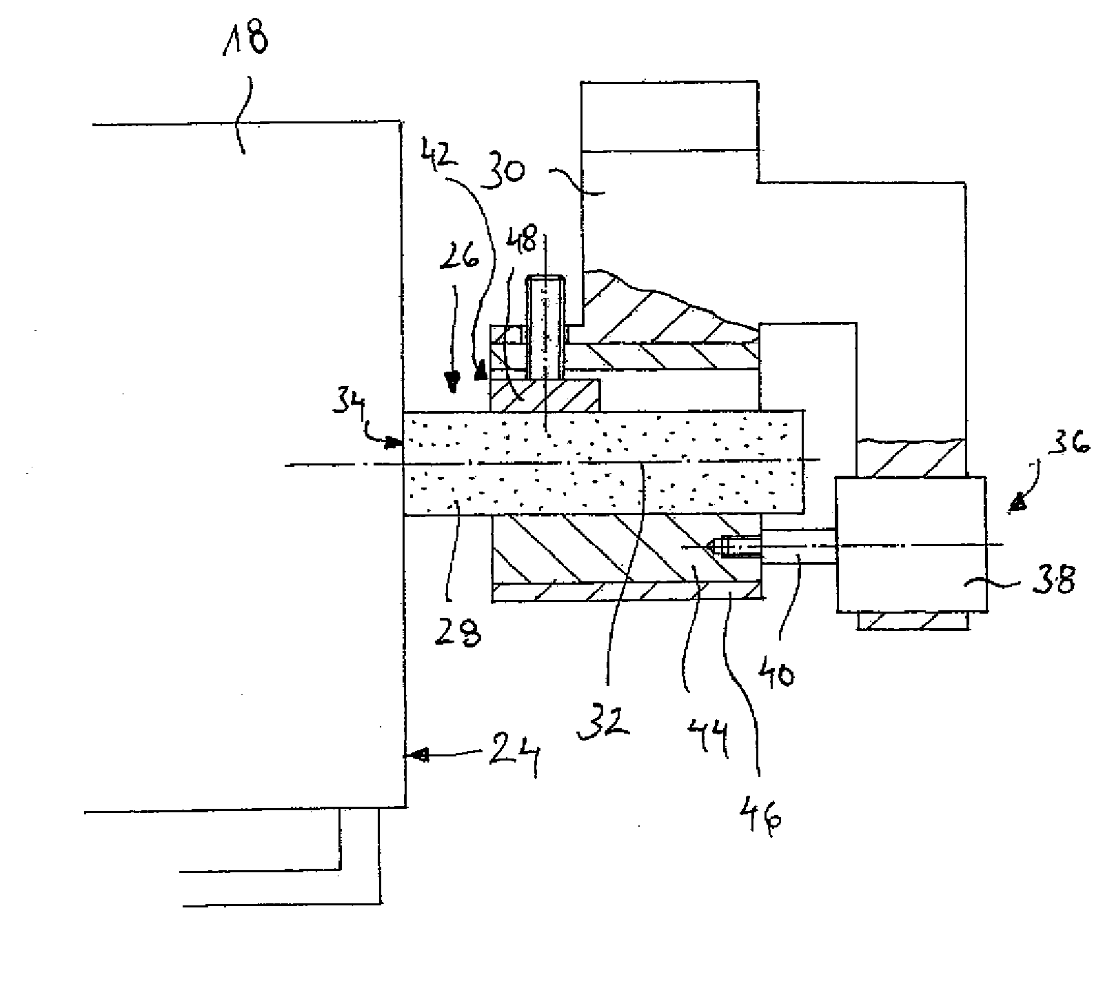
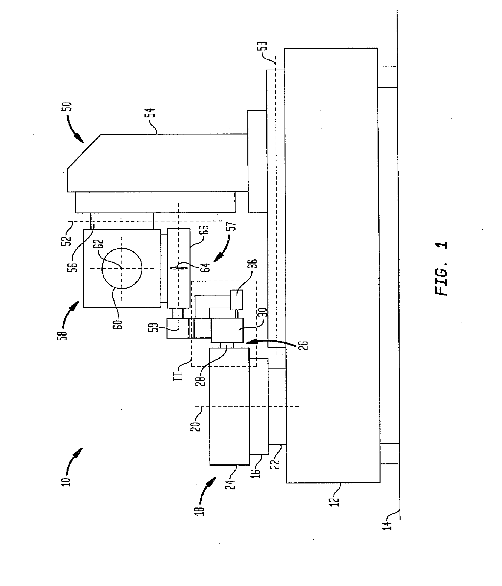
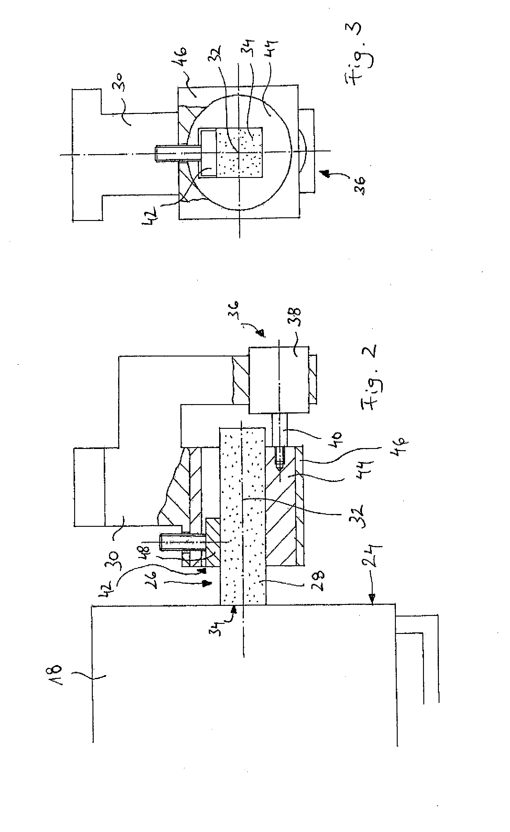
[0063]Throughout all the figures, same or corresponding elements may generally be indicated by same reference numerals. These depicted embodiments are to be understood as illustrative of the invention and not as limiting in any way. It should also be understood that the figures are not necessarily to scale and that the embodiments are sometimes illustrated by graphic symbols, phantom lines, diagrammatic representations and fragmentary views. In certain instances, details which are not necessary for an understanding of the present invention or which render other details difficult to perceive may have been omitted.

[0064]Turning now to the drawing, and in particular to FIG. 1, there is shown a device for finish-machining a workpiece surface, with the device being designated by the reference numeral 10. The device 10 includes a machine frame 12 for placing the device 10 on a supporting surface 14. The frame has a workpiece holder 16 for receiving a workpiece 18 to be finish-machined.

[00...


PUM

PropertyMeasurementUnit
Lengthaaaaaaaaaa
Lengthaaaaaaaaaa
Lengthaaaaaaaaaa

Abstract

A method for finish-machining a workpiece surface includes moving the workpiece surface relative to an active area of the finishing tool in a rotation direction about a workpiece axis, and superimposing on the relative movement of the workpiece surface and the active area an additional oscillatory movement with an oscillation frequency lower than 20 kHz in a direction perpendicular to the workpiece surface.

Description

CROSS-REFERENCES TO RELATED APPLICATIONS[0001]This application claims the priority of European Patent Application, Serial No. 12 164 131.0-2302, filed Apr. 13, 2012, pursuant to 35 U.S.C. 119(a)-(d), the content of which is incorporated herein by reference in its entirety as if fully set forth herein.BACKGROUND OF THE INVENTION[0002]The present invention relates to a method for finishing a workpiece surface with a finishing tool.[0003]The following discussion of related art is provided to assist the reader in understanding the advantages of the invention, and is not to be construed as an admission that this related art is prior art to this invention.[0004]A hybrid technology is known from the project “Ultrasound-assisted Superfinishing of cylindrical precision components (SoFi—Sonic Finish)” wherein a conventional finishing process is combined with an ultrasound machining for precision machining a workpiece. The conventional finishing process includes a rotational movement of the wo...

Claims


Application Information

Patent Timeline
IPC IPC(8): B24B1/04
CPCB24B1/04B24B21/02B24B35/00B24B5/42B24B21/00
Inventor HILDEBRANDT, OLIVER
Owner SUPFINA GRIESHABER
Learn More