Method and apparatus for non-spindle multi-axis machining

a multi-axis, non-spindle technology, applied in the direction of tool holders, manufacturing tools, planing/slotting tools, etc., can solve the problems of limiting the parts it can produce to those with circular cross-sections, affecting the precision of machining, and limiting the productivity of machining, etc., to achieve precise fit and finish, eliminate the chaotic effect of expansive heating and strain hardening, and improve the effect of accuracy

Active Publication Date: 2015-08-11
TENNINE CORP
View PDF38 Cites 9 Cited by
  • Summary
  • Abstract
  • Description
  • Claims
  • Application Information

AI Technical Summary

Benefits of technology

[0006]In order to avoid these shortcomings, the present invention's removal of material by controlled fracturing is useful for a number of reasons: (1) the present invention can remove material from a workpiece at a much higher rate by at least one or two orders of magnitude than prior art machining techniques; (2) the present invention mitigates and sometimes eliminates the chaotic effects of expansive heating and strain-hardening inherent in current methods of contact machining and so is more precise in the fit and finish it imparts to a part; (3) for the same reason, the invention can also produce shapes that are complex (e.g., highly curved airfoiling) and extreme (e.g., very thin cross-sections) that cannot be done using prior art machining methods; and (4) the invention is usable with materials, such as carbon fiber composites, which are typically too brittle for plastic deformation, i.e. their yield strength is identical to their breaking strength and so are difficult or impractical to machine by other prior art methods. Thus, a purpose of the present invention is to profile parts by means of contact machining more rapidly and precisely than existing art, including parts of shapes and materials that are impractical or impossible to profile with using machining techniques presently available in the art.
[0007]Various embodiments of the present invention use non-spindle contact machining not known in prior art to induce controlled fracturing to profile workpieces into finished shapes. The invention combines the superior capabilities of turning and milling without the limitation of either. Generally, a lathe produces parts at faster material removal rates and with finer surface finishes than mill. However, the profiling operation of a lathe is restricted to a two-dimensional work envelope which limits the parts it can produce to those with circular cross-sections. A mill can profile within a three-dimensional work envelope, which permits the production of parts with a greater range of shapes, although at a slower material removal rate and with a rougher finish than a lathe. The present invention combines the advantages of the lathe and the mill in profiling operations without their limitations by producing parts with an unrestricted range of shapes with very fine surface finishes at high rates of material removal.

Problems solved by technology

Because prior art methods of contact machining are restricted to plastic deformation for removing material from a workpiece, complications are inherent in their operation and work to severely restrict performance in terms of productivity, precision, and applicability.
However, the profiling operation of a lathe is restricted to a two-dimensional work envelope which limits the parts it can produce to those with circular cross-sections.
The profiling operations of lathes and mills are limited because they rely upon the torque produced by spindle rotation to cut away material from the workpiece.
However, the need to rotate the cutting tool, which imposes axial symmetry upon it, limits the shape and surface finish that a mill can produce on a workpiece and the material removal rate at which it can do so.
Moreover, the rough surface finish left by milling often necessitates a secondary grinding operation or polishing by hand to create a finer finish on a part, therefore adding time and expense to its production.

Method used


Image

  • Method and apparatus for non-spindle multi-axis machining
  • Method and apparatus for non-spindle multi-axis machining
  • Method and apparatus for non-spindle multi-axis machining

Examples


Embodiment Construction

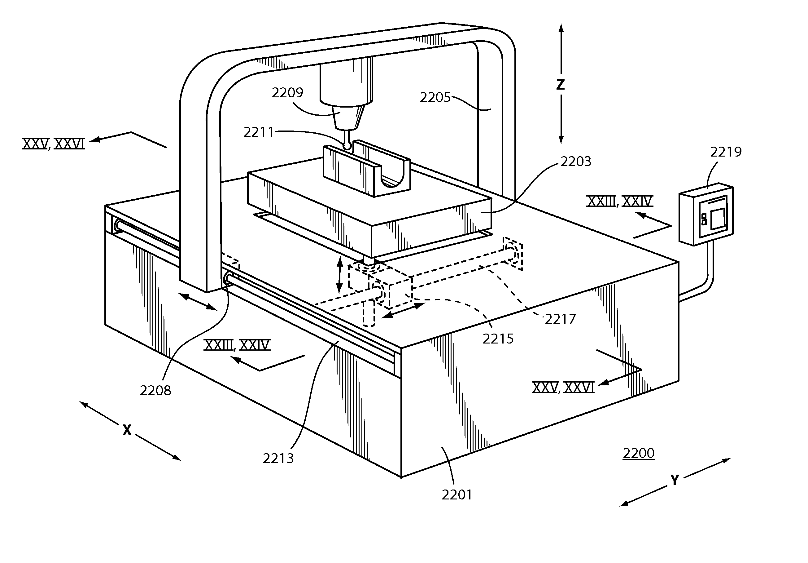
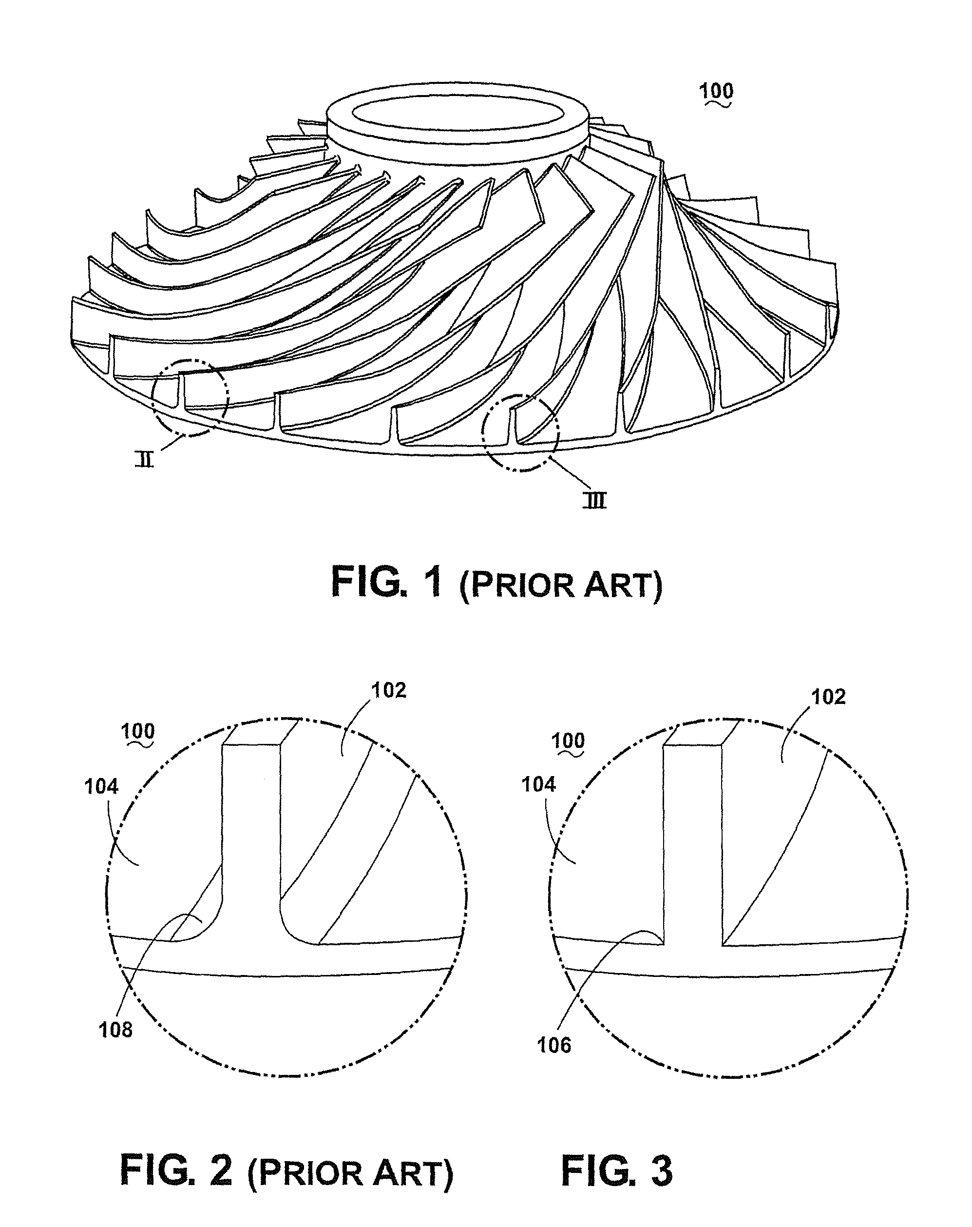
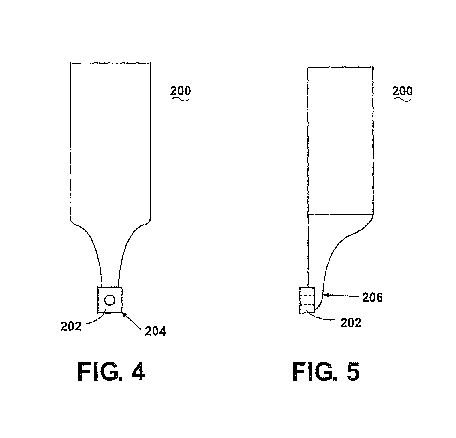
[0040]There are two basic machining operations that are well known in the art. These might be broadly categorized as “profiling” where material is removed from a workpiece to produce a specified shape and surface finish and “holemaking” where material is removed from a workpiece to produce a drilled, tapped, or counter-bored hole. With regard to profiling, in order to profile a workpiece, there are three basic processes for removing material from a workpiece viz. deformation, electrolysis and ablation. Deformation is a process where a cutting tool, having at least one cutting edge, removes material from a workpiece by direct contact. This process is the least restricted in the shapes and materials that can be cut by the cutting tool. The “turning” and “milling” processes are the most common examples of deformation. Electrolysis is a process where a cathode electrochemically dissolves material from an anodized workpiece. This process is restricted to electrically conductive materials...


PUM

PropertyMeasurementUnit
forceaaaaaaaaaa
plastic deformationaaaaaaaaaa
angleaaaaaaaaaa

Abstract

A non-spindle multi-axis machining center (600) and method for forming a part using a non-rotating cutting tool (400) for removing material from a non-rotating workpiece within a three-dimensional work envelope. The non-spindle machining center makes obsolete the use of mills for profiling operations without the need to rotate the cutting tool to produce sufficient torque to remove material. Instead, the cutting tool (400) applies a linear cutting force to the workpiece along a one-, two-, or three-dimensional cutting path with sufficient impact to remove material by means of controlled fracturing instead of plastic deformation. Also, without the need to rotate, neither the cutting tool nor the part are constrained in shape by axial symmetry. Therefore, parts without restrictions in shape can be produced with higher material removal rates and finer surface finishes than by milling or turning.

Description

CROSS-REFERENCE TO RELATED APPLICATIONS[0001]This application is related to U.S. patent application Ser. No. 12 / 520,785 entitled “METHOD AND APPARATUS FOR NON-ROTARY MACHINING.” The aforementioned related application is hereby incorporated by reference in its entirety.FIELD OF THE INVENTION[0002]This invention relates generally to tools and methods for machining parts and, more particularly, to machines that are capable of performing profiling operations.BACKGROUND[0003]Milling is the machining process of using rotary cutters to remove material from a workpiece advancing or feeding in a direction at an angle with the axis of the tool. It covers a wide variety of different operations and machines, on scales from small individual parts to large, heavy-duty gang milling operations. It is one of the most commonly used processes in industry and machine shops today for machining parts to precise sizes and shapes.[0004]Milling can be done with a wide range of machine tools. The original cl...

Claims


Application Information

Patent Timeline
Patent Type & Authority Patents(United States)
IPC IPC(8): B23D5/00B23D7/02B23D3/02
CPCB23D5/00B23D7/02B23D3/02Y10T409/500164Y10T409/502788Y10T409/504592Y10T409/504428Y10T409/502624B23B29/04B23D1/06B23D1/16B23D7/00B23D13/00
Inventor TINGLEY, III, WILLIAM Q.TINGLEY, WILLIAM Q.BRADLEY, DANIEL R.
Owner TENNINE CORP
Why Eureka
Try Eureka