
Wiring substrate

a technology of wire substrate and wire, which is applied in the direction of resisting details, sustainable manufacturing/processing, and final product manufacturing, etc., can solve the problem of solder bump connection failur

Active Publication Date: 2014-05-22
SHINKO ELECTRIC IND CO LTD
View PDF5 Cites 11 Cited by
  • Summary
  • Abstract
  • Description
  • Claims
  • Application Information

AI Technical Summary

Benefits of technology

The present invention provides a wiring substrate with a reliable bump electrode on a connection pad exposed from an opening portion of a protective insulation layer. This allows for a more reliable connection between the wiring substrate and other components.

Problems solved by technology

Such an intermetallic compound is mechanically brittle and thus easily damaged by external stress, which may lead to a connection failure of the solder bump.

Method used


Image

  • Wiring substrate
  • Wiring substrate
  • Wiring substrate

Examples


Embodiment Construction

[0019]In the following, embodiments according to the present invention will be described with reference to the accompanying drawings.

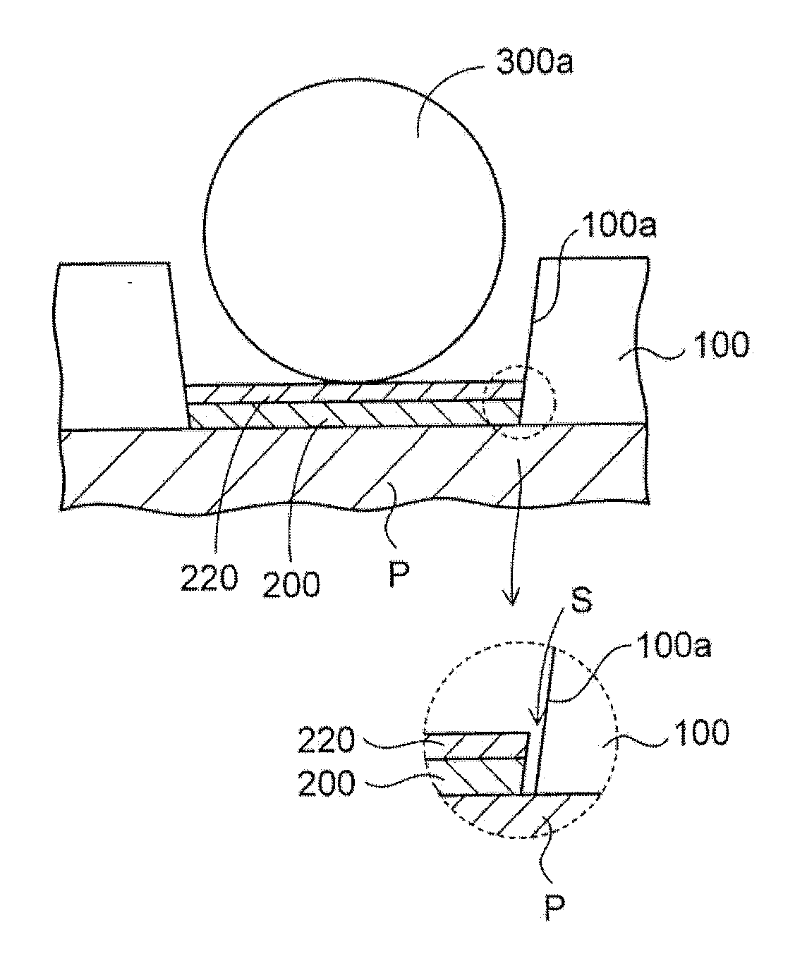
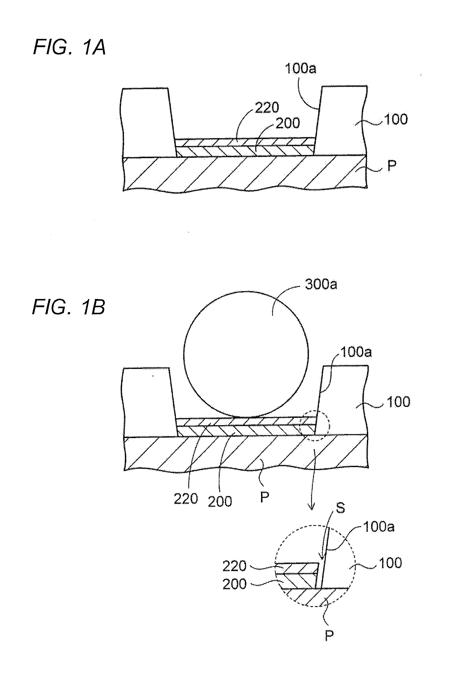
[0020]First, an introduction section will be explained for better understanding of the present invention, before detailed description of embodiments according to the present invention is given. FIGS. 1A and 1B partially illustrate a connection pad in a wiring substrate. Referring to FIG. 1A, the wiring substrate is provided with a connection pad P that is formed of copper and electrically connected to a multi-layer wiring (not illustrated), and a solder resist 100 that includes an opening portion 100a and formed on the connection pad P.

[0021]On the connection pad P which is exposed from the opening portion 100a of the solder resist 100, a nickel layer 200 and a gold layer 220 are formed in this order from the bottom by a non-electrolytic plating process. The nickel layer 200 is formed so as to serve as a barrier metal layer, and the gold layer 220 is f...


PUM


Abstract

A wiring substrate includes: a connection pad having a first surface; a protective insulation layer formed on the first surface of the connection pad and having an opening portion therein, wherein a portion of the first surface of the connection pad is exposed from the opening portion; a metal layer having a lower surface facing the first surface of the connection pad and an upper surface opposite to the lower surface and formed on the first surface of the connection pad which is exposed from the opening portion, the metal layer including a raised portion that extends upward from the upper surface of the metal layer in a peripheral portion thereof; and a bump electrode formed on the upper surface of the metal layer.

Description

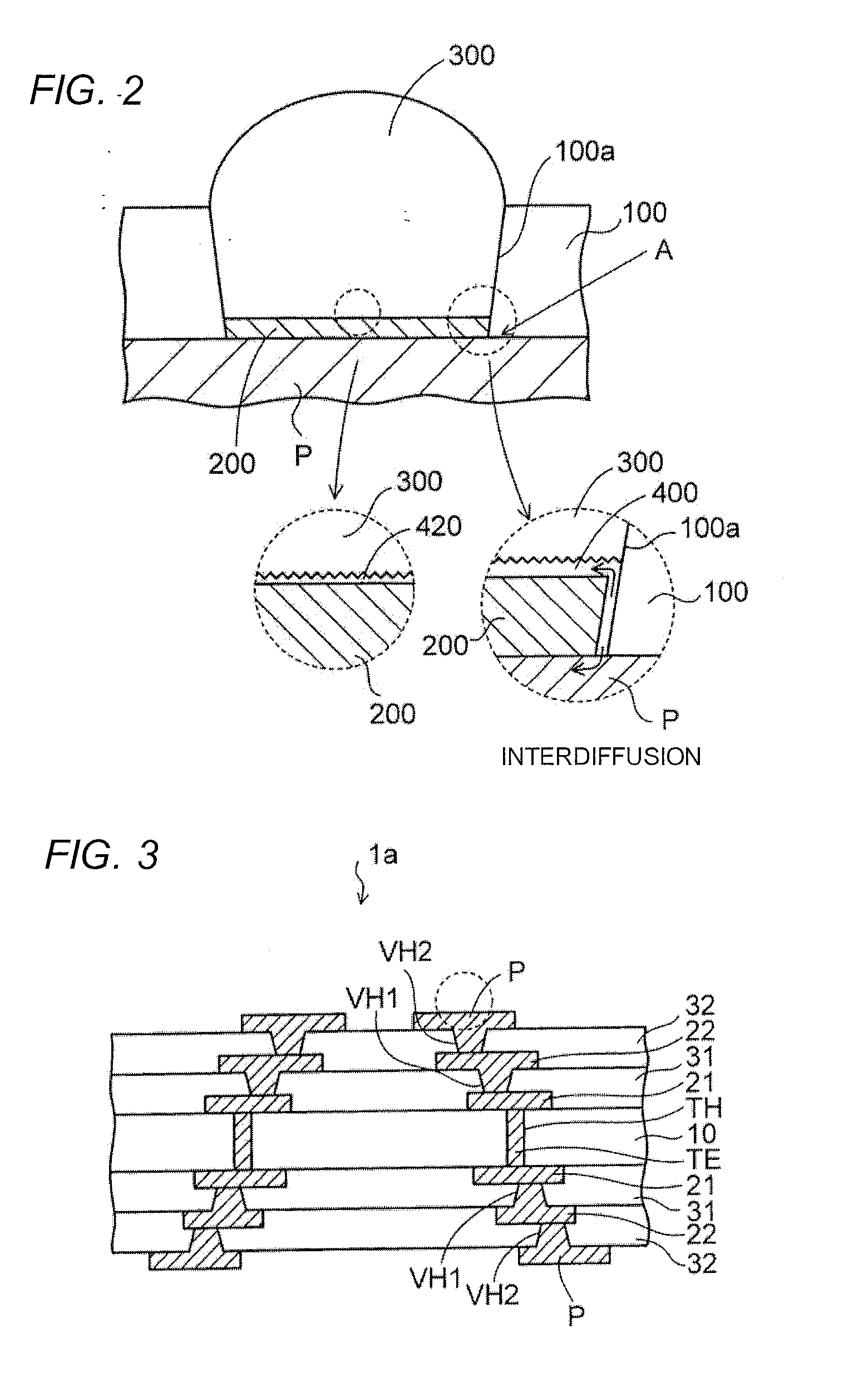
[0001]This application claims priority from Japanese Patent Application No. 2012-255040, filed on Nov. 21, 2012, the entire contents of which are herein incorporated by reference.BACKGROUND[0002]1. Technical Field[0003]The present disclosure relates to a wiring substrate.[0004]2. Description of Related Art[0005]There have been known wiring substrates on which an electronic component such as a semiconductor chip is mounted. When solder bumps are provided on connection pads on such a wiring substrate, surface treatment layers such as a nickel layer / gold layer are formed on upper surfaces of the connection pads (see e.g., JP-A-2001-60760).[0006]As described in an introduction section for explaining the present invention (see later), when producing the wiring substrate, a solder bump is formed on a connection pad exposed from an opening portion of a solder resist via a nickel layer. In this case, tin contained in the solder and copper contained in the connection pad are diffused through...

Claims


Application Information

Patent Timeline
Patent Type & Authority Applications(United States)
IPC IPC(8): H05K1/11
CPCH05K1/111H01L2224/16225H01L2224/32225H01L2224/73204H01L2924/15174H01L2924/15311H05K3/3452H05K3/4007H05K3/4682H05K2201/0373H05K2201/0769H05K2201/099H05K2201/2072H05K2203/0594H05K2203/1184H05K1/11Y02P70/50H01L2924/00
Inventor IMAFUJI, KEIYOSHIIKE, JUN
Owner SHINKO ELECTRIC IND CO LTD
Learn More