Power transmitting device and power transfer system

a power transmission device and power transfer technology, applied in the direction of charging stations, rail devices, transportation and packaging, etc., can solve the problems of power transmission device high cost and power transmission efficiency decline, and achieve high-efficiency power transmission and cost reduction

Inactive Publication Date: 2014-05-22
TOYOTA JIDOSHA KK
View PDF25 Cites 28 Cited by
  • Summary
  • Abstract
  • Description
  • Claims
  • Application Information

AI Technical Summary

Benefits of technology

[0011]The invention provides a power transmitting device and a power transfer system that are able to obtain high power transfer efficiency at the time when a vehicle approaches a location at which a plurality of primary coils are provided, then stops and receives electric power in a stopped state, and are able to reduce manufacturing cost.
[0024]With the power transmitting device and the power transfer system according to the aspects of the invention, it is possible to achieve high-efficiency power transfer and to reduce cost.

Problems solved by technology

Therefore, the power transmitting device becomes very expensive.
However, if the number of power transmitting-side communication means is reduced, there occurs a positional deviation between the power receiving antenna and the power transmitting antennas, with the result that power transfer efficiency decreases.

Method used


Image

  • Power transmitting device and power transfer system
  • Power transmitting device and power transfer system
  • Power transmitting device and power transfer system

Examples


first embodiment

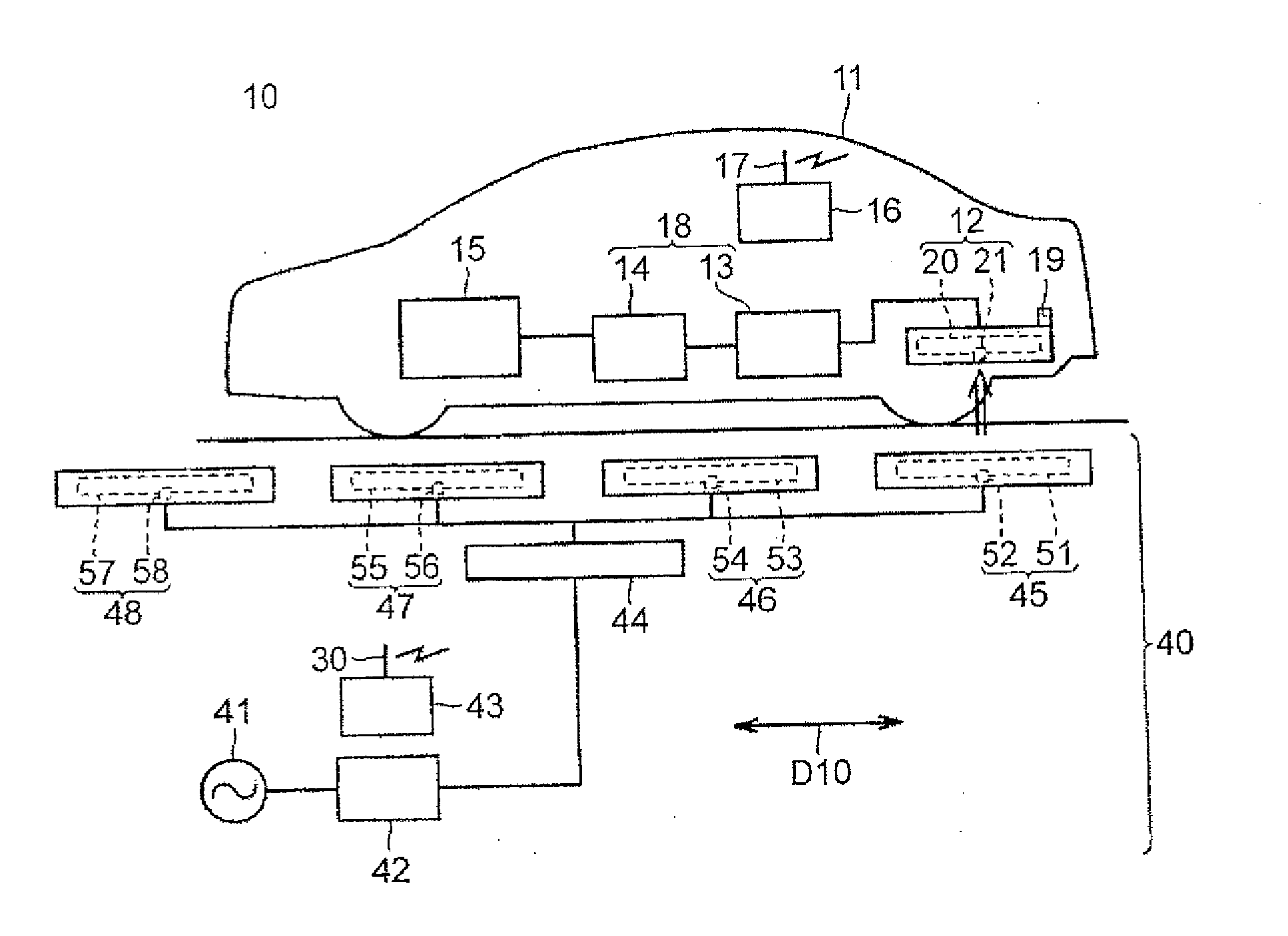
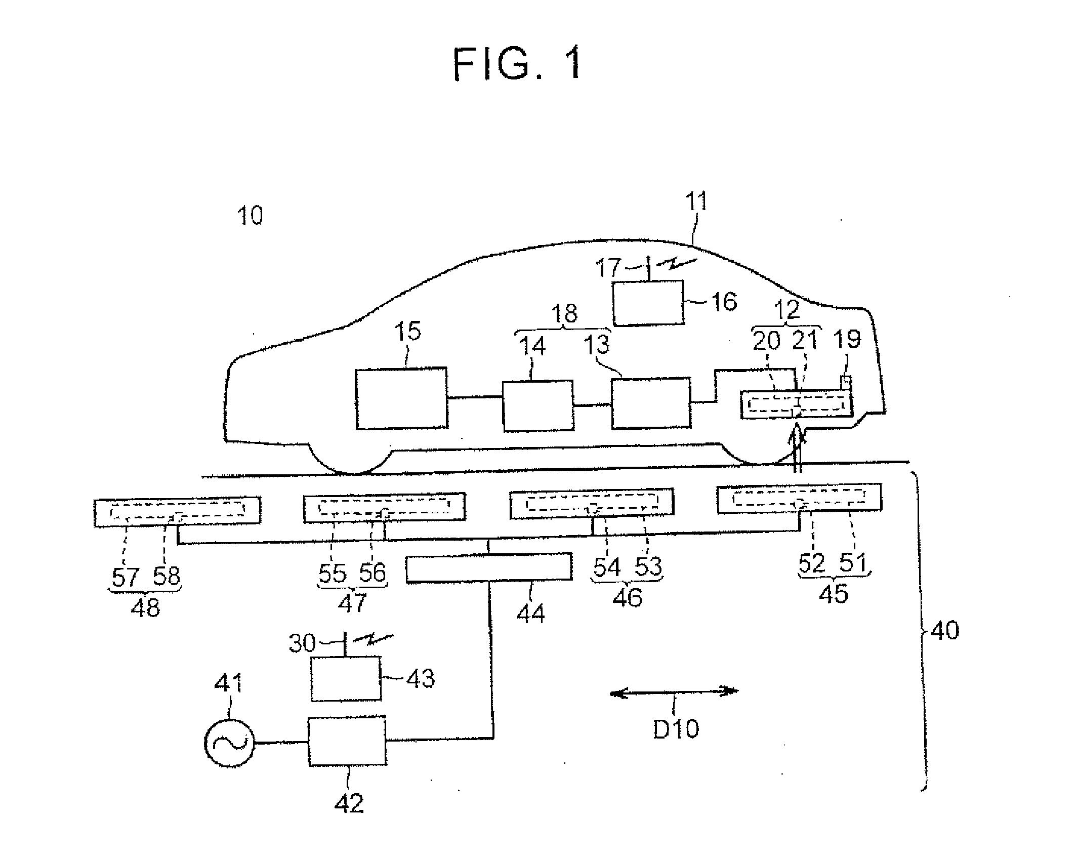
[0049]Hereinafter, embodiments of the invention will be described in detail with reference to the accompanying drawings. Like reference numerals denote the same or corresponding components in the drawings, and the description thereof is not repeated. A first embodiment will be described first. FIG. 1 is an overall block diagram that shows an example of a contactless power transfer system. A vehicle 11 is illustrated as an electric vehicle that uses a rotary electric machine as a drive source; however, as long as the vehicle 11 contactlessly receives electric power, the vehicle 11 may be another automobile or a power receiving object may not be a vehicle.

[0050]As shown in FIG. 1, a contactless power transfer system 10 includes a power transmitting device 40 and the vehicle 11. The power transmitting device 40 includes a communication unit 30, a power supply unit 42, a power transmitting-side control unit 43, a selecting unit 44 and a plurality of power transmitting units 45, 46, 47, ...

second embodiment

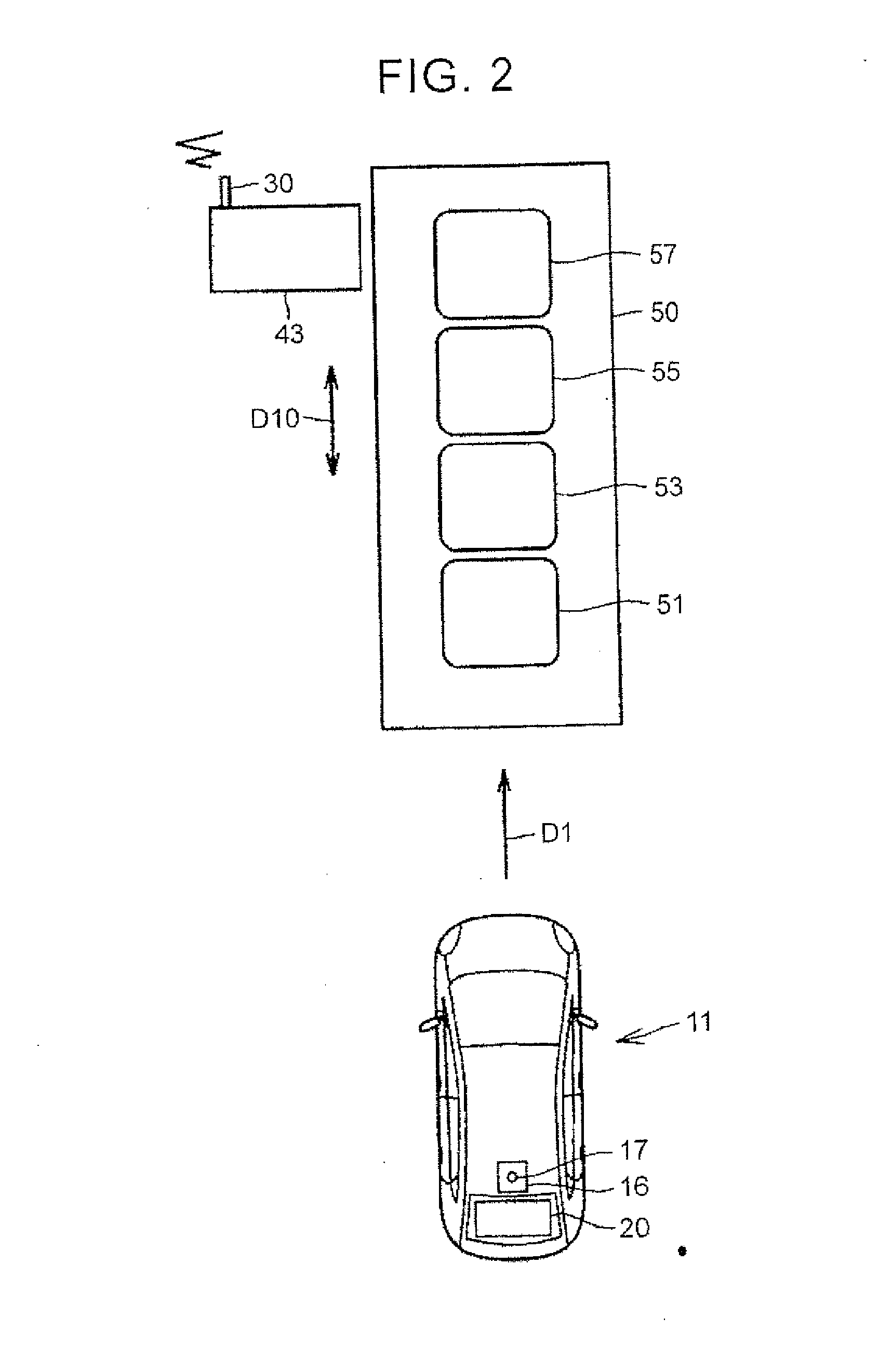
[0099]Subsequently, a power transmitting device, a power receiving device and a power transfer system will be described with reference to FIG. 10 to FIG. 13. FIG. 10 is a plan view that schematically shows the vehicle 11 and the power transmitting device 40.

[0100]In the power transmitting device 40 according to the second embodiment, a plurality of primary coils 51, 53, 55, 57, 59 are arranged at intervals in the arrangement direction D10. The arrangement direction D10 is the longitudinal direction of the vehicle 11 stopped within the parking lot 50.

[0101]Among the plurality of primary coils 51, 53, 55, 57, 59, the primary coil 55 located at the center in the arrangement direction D10 is a center coil.

[0102]The power transmitting device 40 according to the second embodiment supplies the second electric power to the center coil (i.e. primary coil 55) at the time when the power transmitting device 40 starts control for selecting the power transmitting coil that is supplied with the f...

third embodiment

[0134]When the power transmitting device 40 determines that a power transmitting situation between the current power transmitting coil and the secondary coil 20 does not satisfy a power transmitting condition after supply of the first electric power to the power transmitting coil has been started, the power transmitting device 40 stops transmission of electric power from the power transmitting coil to the secondary coil 20. After that, the primary coil having a power receiving efficiency higher than the threshold is selected from among the plurality of primary coils, the first electric power is supplied to the selected primary coil, and transfer of electric power to the secondary coil 20 is resumed.

[0135]The fact that the power transmitting situation does not satisfy the power transmitting condition includes a case where the temperature of the power transmitting coil has exceeded a threshold, a case where the distance between the power transmitting coil and the secondary coil 20 ha...


PUM

PropertyMeasurementUnit
electric poweraaaaaaaaaa
power receiving efficiencyaaaaaaaaaa
timeaaaaaaaaaa

Abstract

A power transmitting device that contactlessly transmits electric power to a power receiving device having a secondary coil provided at a vehicle, and a power transfer system, are provided. The power transmitting device includes primary coils, a selecting unit and a control unit. The primary coils are arranged at an interval in an arrangement direction. The selecting unit selects one primary coil to which electric power is supplied from a power supply. The control unit controls the selecting unit by supplying the selected primary coil with a second electric power smaller than a first electric power, selecting a power transmitting coil from among the primary coils on the basis of at least one of a power transmitting situation of the selected primary coil and a power receiving situation of the secondary coil, and supplying the power transmitting coil with the first electric power.

Description

INCORPORATION BY REFERENCE[0001]The disclosure of Japanese Patent Application No. 2012-255003 filed on Nov. 21, 2012 including the specification, drawings and abstract is incorporated herein by reference in its entirety.BACKGROUND OF THE INVENTION[0002]1. Field of the Invention[0003]The invention relates to a power transmitting device and a power transfer system.[0004]2. Description of Related Art[0005]As is described in Japanese Patent Application Publication No. 2010-172084 (JP 2010-172084 A) and Japanese Patent Application Publication No. 2010-239777 (JP 2010-239777 A), there is known a contactless power supply system that contactlessly transmits electric power.[0006]In recent years, a road-to-vehicle power supply system in which a plurality of power transmitting devices are embedded in a road surface and a power receiving device provided at a vehicle contactlessly receives electric power from any one of the power transmitting devices has become a focus of attention.[0007]For exa...

Claims


Application Information

Patent Timeline
Patent Type & Authority Applications(United States)
IPC IPC(8): B60L5/00H02J7/02H02J7/00B60M7/00H01F38/14
CPCB60M7/003B60L2240/80Y02T90/14Y04S30/14B60L53/30B60L53/39B60L53/36B60L53/65B60L53/305B60L5/005B60L53/126B60L53/124B60L53/122Y02T10/7072Y02T90/12Y02T90/167Y02T90/16Y02T10/70H02J50/90H02J50/80H02J50/12
Inventor ICHIKAWA, SHINJINAKAMURA, TORU
Owner TOYOTA JIDOSHA KK
Why Eureka
Try Eureka