Gas spring with dampening

a technology of pneumatic springs and dampening springs, which is applied in the direction of springs, vibration dampers, gas based dampers, etc., can solve the problems of high production cost, complex production, and the mention of solutions according to the state of the ar

Inactive Publication Date: 2014-05-22
KRISLO MICHAL +1
View PDF7 Cites 8 Cited by
  • Summary
  • Abstract
  • Description
  • Claims
  • Application Information

AI Technical Summary

Benefits of technology

[0031]It is also of advantage that such a gas spring can be, depending on its use, constituted either as a compression spring, where the working gas in both chambers, i.e. in the working cylinder as well as in the reservoir, is under a pressure that is higher than the pressure of the surroundings, or as an extension spring, where there is a negative pressure in both chambers.

Problems solved by technology

All of the above-mentioned solutions according to the state of the art are complex from the constructional point of view and involve many individual elements; in many cases they combine a gas spring (generally air spring) or a steel spring with an oil damper.
Hence, these solutions are complicated to produce and their cost of production is high.

Method used


Image

  • Gas spring with dampening
  • Gas spring with dampening
  • Gas spring with dampening

Examples


Embodiment Construction

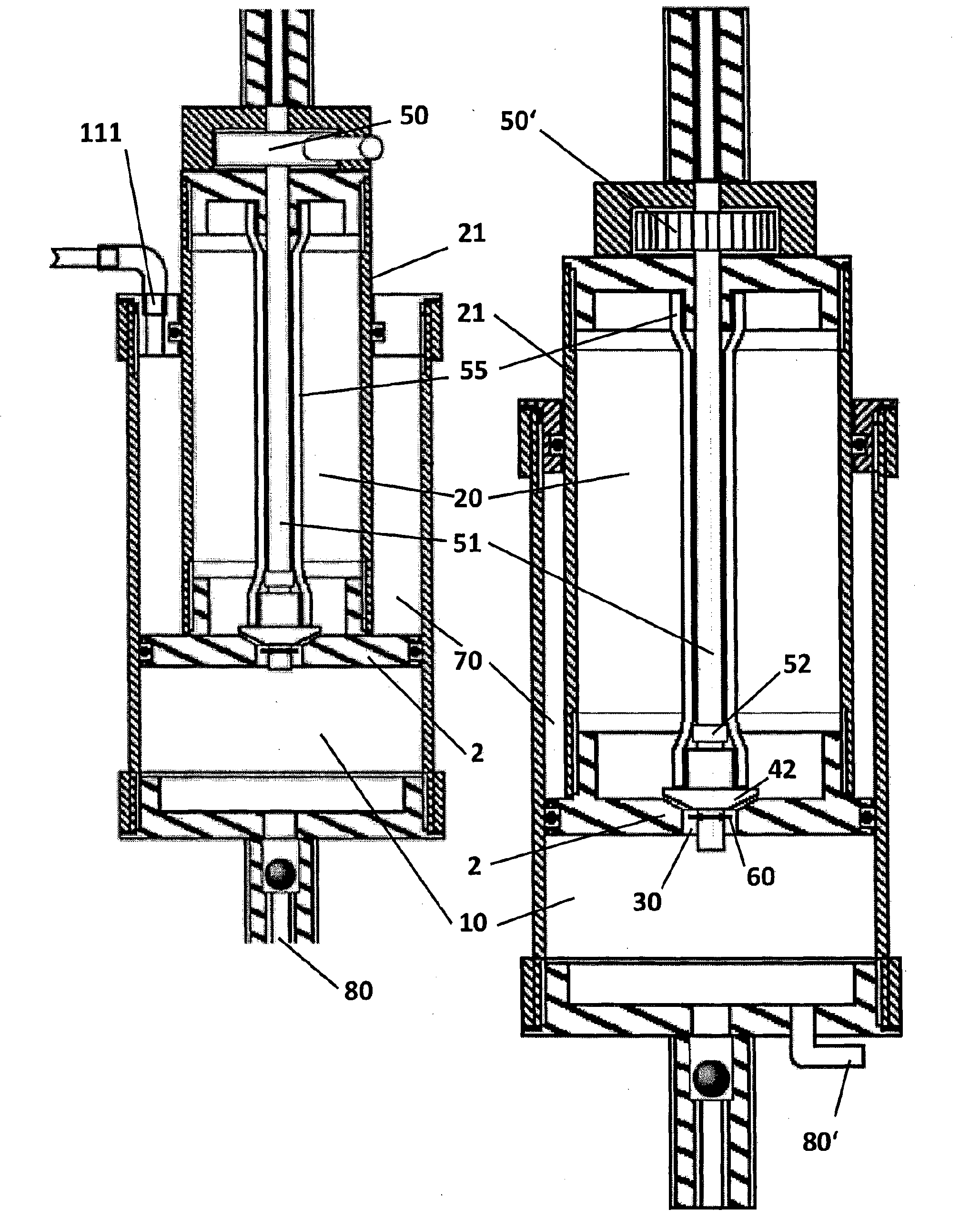
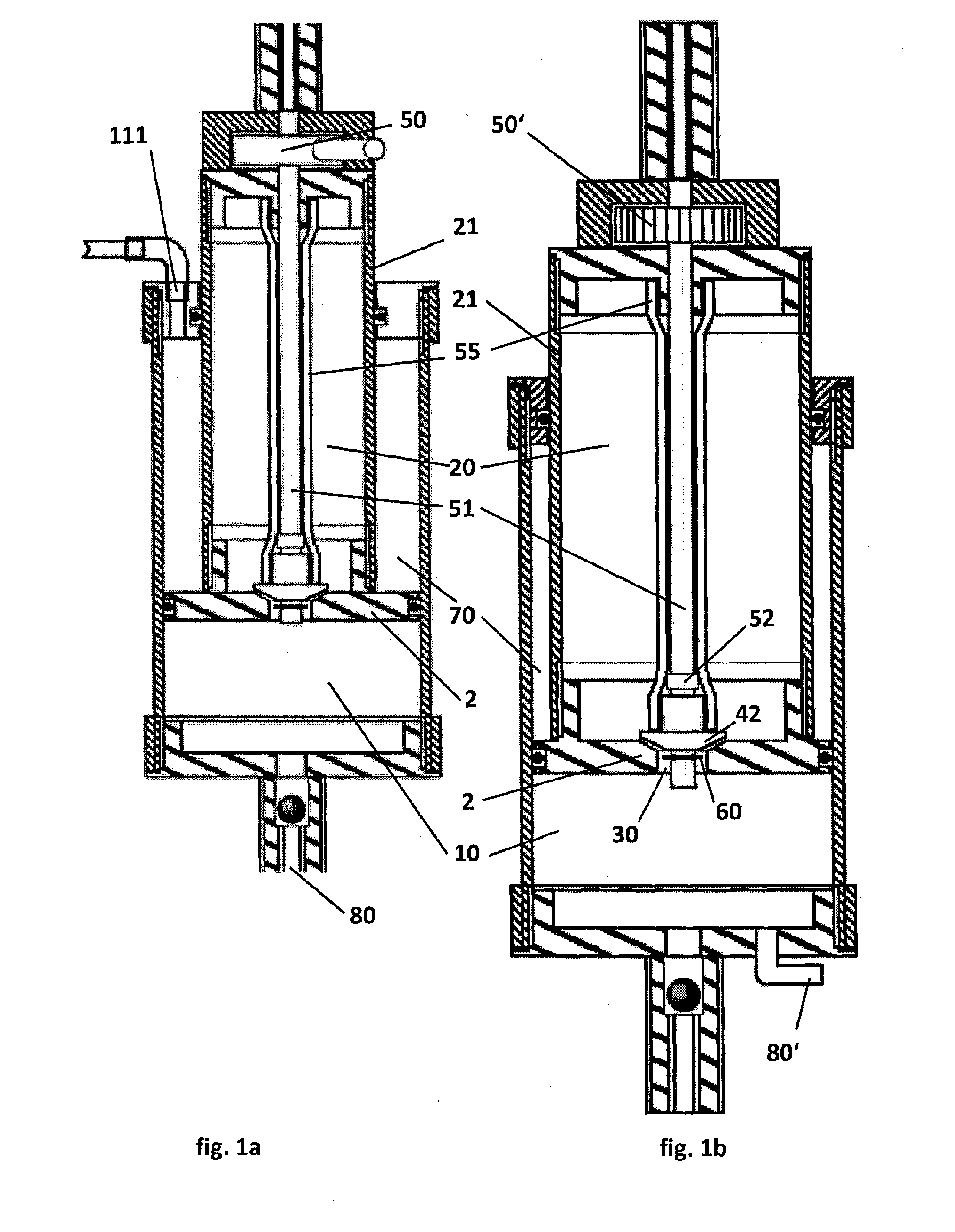
[0043]The device in FIG. 1 consists of the working cylinder 10 and the reservoir 20 (or transfer cylinder) constituted by the storage cylinder 21, which constitutes the piston rod, a piston 2 being arranged on its lower end, this piston at the same time closing up the storage cylinder 21 on the lower end. On the upper end, the reservoir 20 being closed up by a cover, with which cover an attachment of the gas spring for coupling with the piece, for which a suspension has to be provided, is connected. An opposite attachment is arranged on the lower cover of the working cylinder 10, in which cover at the same time a filling valve 80 is established. Hence, the working cylinder is positioned outside of the storage cylinder and between both these cylinders a transfer opening 30 is created. All the expressions such as upper, lower, or up and down, and others, as being used throughout this text, refer only to the illustration of the exemplary embodiment as shown on the attached drawings, an...


PUM


Abstract

This invention concerns a gas spring having a working cylinder and therein a slidably arranged piston, whereas the working gas is, in order to provide for springing and dampening, optionally transferable between the working cylinder and the reservoir, characterized in that the reservoir is arranged in the piston rod. The gas or air spring according to this invention is self-dampening in both directions, i.e. at compression as well as at the extension. At compression it behaves as an air spring with dampening and at the extension it also behaves as an air spring with dampening, whereas both these damping effects can be, as regards the magnitude of the dampening, controlled independently from each other.

Description

FIELD OF THE INVENTION[0001]This invention concerns gas (pneumatic) spring with dampening, in which working gas can optionally be transferred between the working cylinder and a reservoir (or transfer cylinder) in order to provide springing and dampening of the return.BACKGROUND OF THE INVENTION[0002]In the prior art, and the automotive industry in particular, a variety of solutions for gas springs with dampening is known.[0003]Firstly, document GB 1 520 028 describes a lockable pneumatic (or hydro-pneumatic) spring, in which dampening occurs based on the transfer through the piston body. However, the chamber into which it is transferred is not located in the piston rod. The hollow piston rod is only used here to fill such a spring. As a result of this, such a spring not only lacks compaction but, more importantly, the working length of such a spring is significantly reduced.[0004]Document U.S. Pat. No. 3,059,916 describes an air shock absorber for a vehicle—i.e. air damper—with regu...

Claims


Application Information

Patent Timeline
Patent Type & Authority Applications(United States)
IPC IPC(8): F16F9/02F16F9/43F16F9/512F16F9/36F16F9/34
CPCF16F9/0236F16F9/34F16F9/512F16F9/43F16F9/36F16F9/44
Inventor KNOBLOCH, RAFAEL
Owner KRISLO MICHAL
Why Eureka
Try Eureka