Multilevel inverter

a multi-level inverter and inverter technology, applied in the direction of electronic commutation motor control, motor/generator/converter stopper, dynamo-electric converter control, etc., can solve the problems of complex circuit for stopping the functioning, inability to safely stop the functioning, increase the breakdown rate and safety, and achieve the effect of avoiding the destruction of switching elements

Active Publication Date: 2014-05-22
FUJI ELECTRIC CO LTD
View PDF3 Cites 13 Cited by
  • Summary
  • Abstract
  • Description
  • Claims
  • Application Information

AI Technical Summary

Benefits of technology

[0019]As heretofore described, the invention is such that, in relation to a multilevel inverter of three levels or more,

Problems solved by technology

In this case, even when the switching element connected to one terminal among the positive terminal, negative terminal, and intermediate terminal is disabled, there is conduction between the other two terminals, meaning that it is not possible to safely stop the functioning unless the switching elements

Method used


Image

  • Multilevel inverter
  • Multilevel inverter
  • Multilevel inverter

Examples


first embodiment

Inverter 100

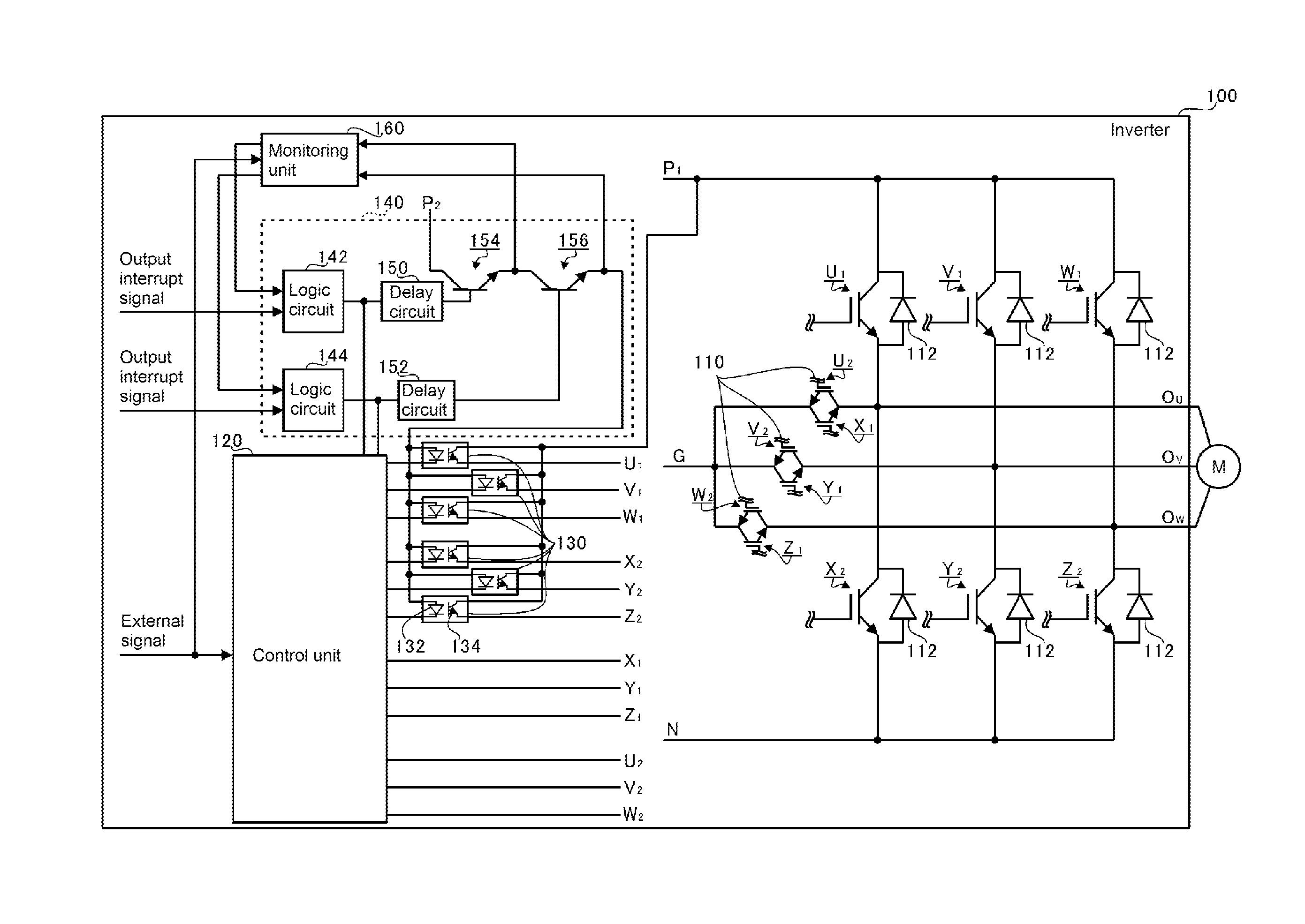
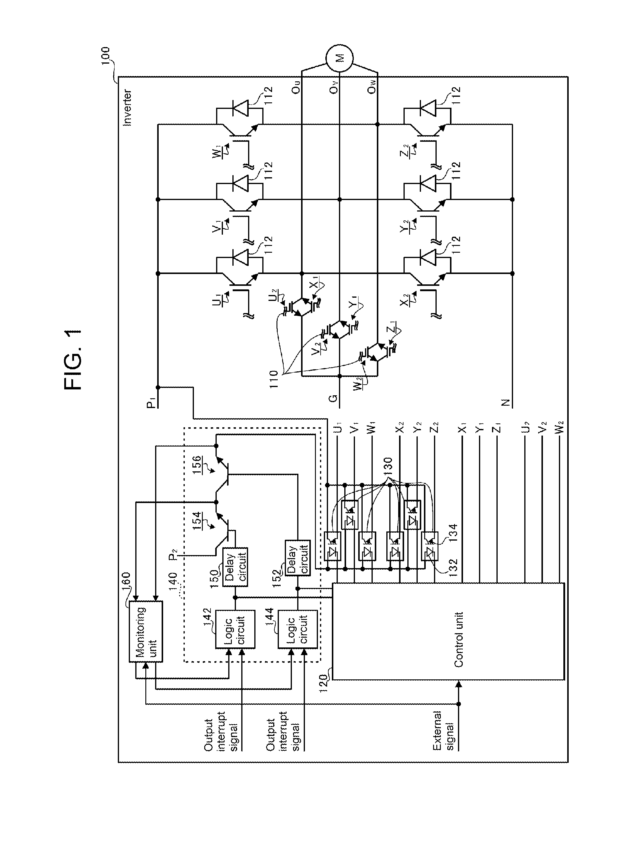
[0028]FIG. 1 is an illustration showing a schematic configuration of an inverter 100 in a first embodiment. The inverter 100 is configured to include direct current input terminals (a positive terminal P1, a negative terminal N, and an intermediate terminal G), switching elements (first switching elements U1, V1, and W1 and second switching elements X2, Y2, and Z2), reverse blocking switching elements 110, freewheeling diodes 112, a control unit 120, photocouplers 130, a control signal interrupt circuit 140, delay circuits 150 and 152, and a monitoring unit 160. The term “insulated gate bipolar transistor” (IGBT) is used for each switching element terminal.

[0029]The inverter 100 of this embodiment is an inverter including a plurality of direct current input terminals disposed in order of descending potential from first to nth (n is an odd number of 3 or more). Herein, a three-level inverter wherein n is 3, that is, including a first direct current input terminal (the pos...

second embodiment

Inverter 200

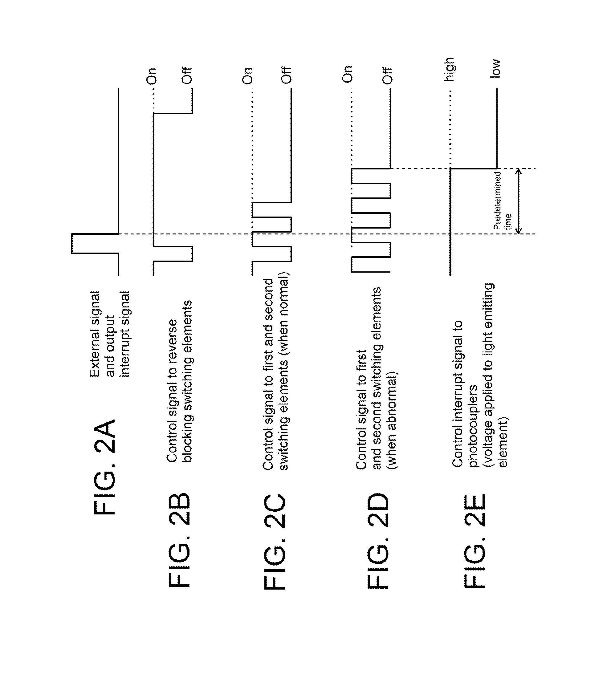
[0071]The first embodiment is such that the photocouplers 130 are included, and the control signal interrupt circuit 140 stops the application of voltage to the photocouplers 130. A description has been given of a case wherein, by so doing, the process of turning off the first switching elements U1, V1, and W1 and second switching elements X2, Y2, and Z2 is implemented. In a second embodiment, three-state circuits 230 and 232 are included instead of the photocouplers 130. Further, a description will be given of a case wherein a control signal interrupt circuit 240 implements the process of turning off the first switching elements U1, V1, and W1 and second switching elements X2, Y2, and Z2 via the three-state circuits 230 and 232. In the second embodiment, the same reference signs are given to configurations the same as those in the first embodiment, and a detailed description thereof is omitted.

[0072]FIG. 4 is an illustration showing a schematic configuration of an inver...

third embodiment

Inverter 300

[0089]In the first and second embodiments, descriptions have been given of the inverters 100 and 200, which are three-level inverters. In a third embodiment, a description will be given of an inverter 300, which is a five-level inverter. In the third embodiment, the same reference signs are given to configurations the same as those in the first and second embodiments, and a detailed description thereof is omitted.

[0090]FIG. 6 is a first drawing showing a schematic configuration of the inverter 300 in the third embodiment, while FIG. 7 is a second drawing showing a schematic configuration of the inverter 300 in the third embodiment. Herein, as each drawing is shown enlarged so as to facilitate understanding, one inverter 300 is shown divided between two drawings. Also, in FIGS. 6 and 7, a connection path from a control unit 320 shown in FIG. 6 to each switching element shown in FIG. 7 is shown with one portion omitted in order to facilitate understanding.

[0091]As shown in...


PUM


Abstract

In relation to a multilevel inverter of three levels or more, a decrease in safety due to breakdown is suppressed while avoiding destruction of switching elements. An inverter includes switching elements connected in series between a positive terminal and a negative terminal, reverse blocking switching elements connected one each between connection points of pairs of the switching elements and an intermediate terminal, alternating current output terminals, a control unit that generates control signals for switching between a turning on and turning off of the plurality of switching elements, a control signal interrupt circuit that, on an interrupt signal interrupting the output voltage of the alternating current output terminals being input, interrupts each of the control signals to the first switching elements and second switching elements, regardless of the state of the control signals, and a monitoring unit that diagnoses a breakdown of the control signal interrupt circuit.

Description

BACKGROUND OF THE INVENTION[0001]1. Field of the Invention[0002]The present invention relates to a multilevel inverter that converts direct current power to alternating current power.[0003]2. Description of the Background Art[0004]In relation to an inverter that converts direct current power to alternating current power, the spread of a multilevel inverter wherein connections to a positive terminal, negative terminal, and intermediate terminal to which direct current voltage is applied are switched by switching elements (semiconductor switches) is increasing. As the switching voltage in the switching element connected to the intermediate terminal is low compared with that in the switching elements connected to the positive terminal and negative terminal, it is possible to select a switching element with low rated voltage, and thus possible to employ a switching element with comparatively good electrical characteristics.[0005]However, in the event that all the switching elements are ...

Claims


Application Information

Patent Timeline
IPC IPC(8): H02P3/02
CPCH02P3/02H02M1/32H02M7/487H02M1/36H02M1/007H02M1/0095
Inventor SATO, IKUYA
Owner FUJI ELECTRIC CO LTD
Why Eureka
Try Eureka