
Turbocharger

Active Publication Date: 2014-05-22
IHI CORP
View PDF7 Cites 5 Cited by
  • Summary
  • Abstract
  • Description
  • Claims
  • Application Information

AI Technical Summary

Benefits of technology

The turbocharger in this invention prevents droplets from staying in a return passage in the compressor housing. This means that the turbocharger prevents waterdrops from getting stuck in the air compressor and causing damage.

Problems solved by technology

In this case, in a cold area, it is likely that a sufficient amount of air cannot be returned to the upstream side because the droplets staying in the return passage get frozen and thereby narrow the return passage, for instance.
Furthermore, residue remaining in the return passage may become viscous through evaporation of the moisture.
When the viscous residue sticks between the air bypass valve and the seat surface, the residue may hinder the air bypass valve from being opened and closed normally.

Method used


Image

  • Turbocharger
  • Turbocharger
  • Turbocharger

Examples


Embodiment Construction

[0014]Referring to the accompanying drawings, descriptions will be hereinbelow provided for a preferred embodiment of the present invention. Dimensions, materials, specific values and the like shown in the embodiment are provided just as examples for facilitating understanding of the invention, and are not intended to limit the present invention unless otherwise specified. In the specification and drawings, components having substantially the same functions and configurations will be denoted by the same reference signs and duplicated explanations will thus be omitted. Meanwhile, illustration of components not directly related to the present invention is omitted.

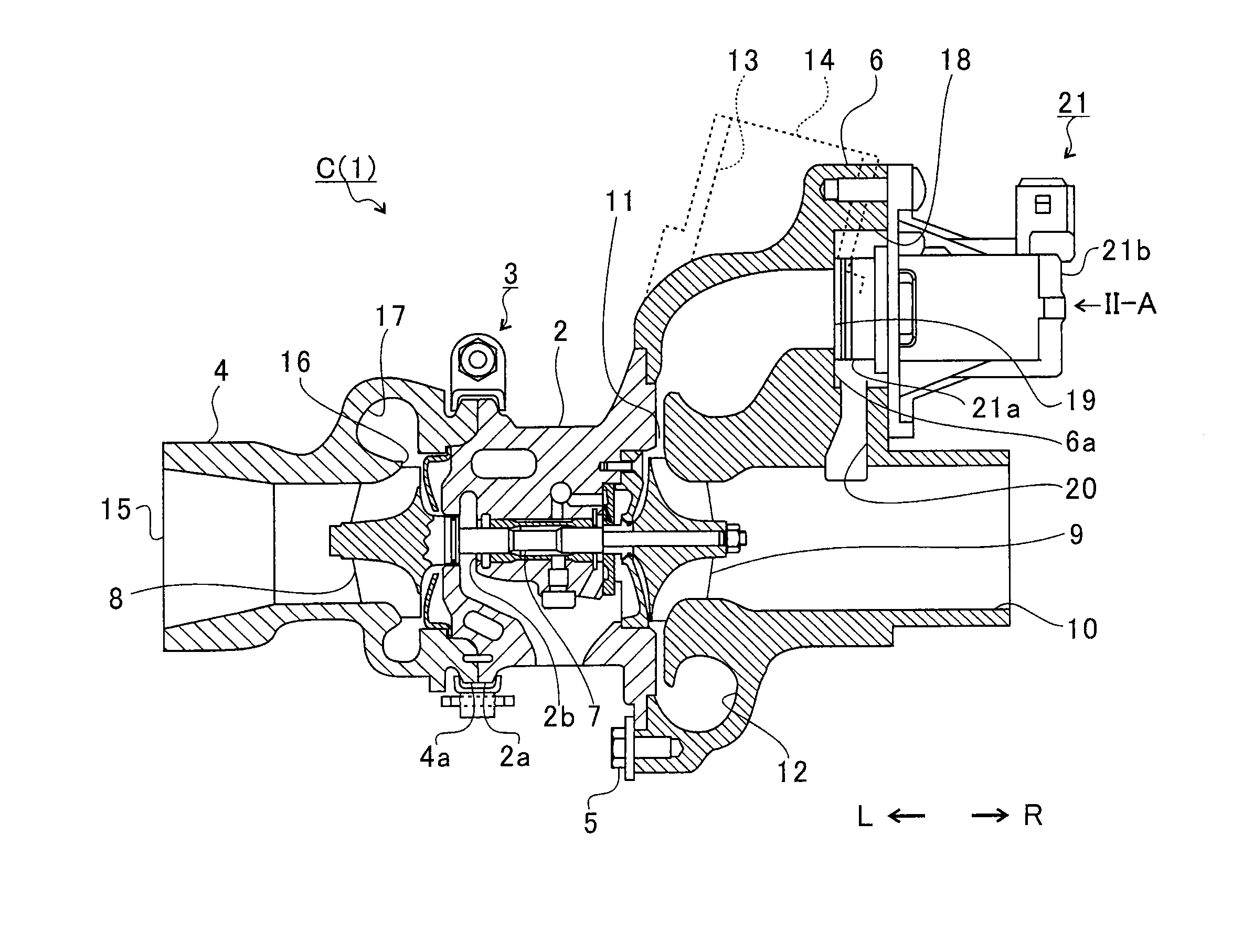
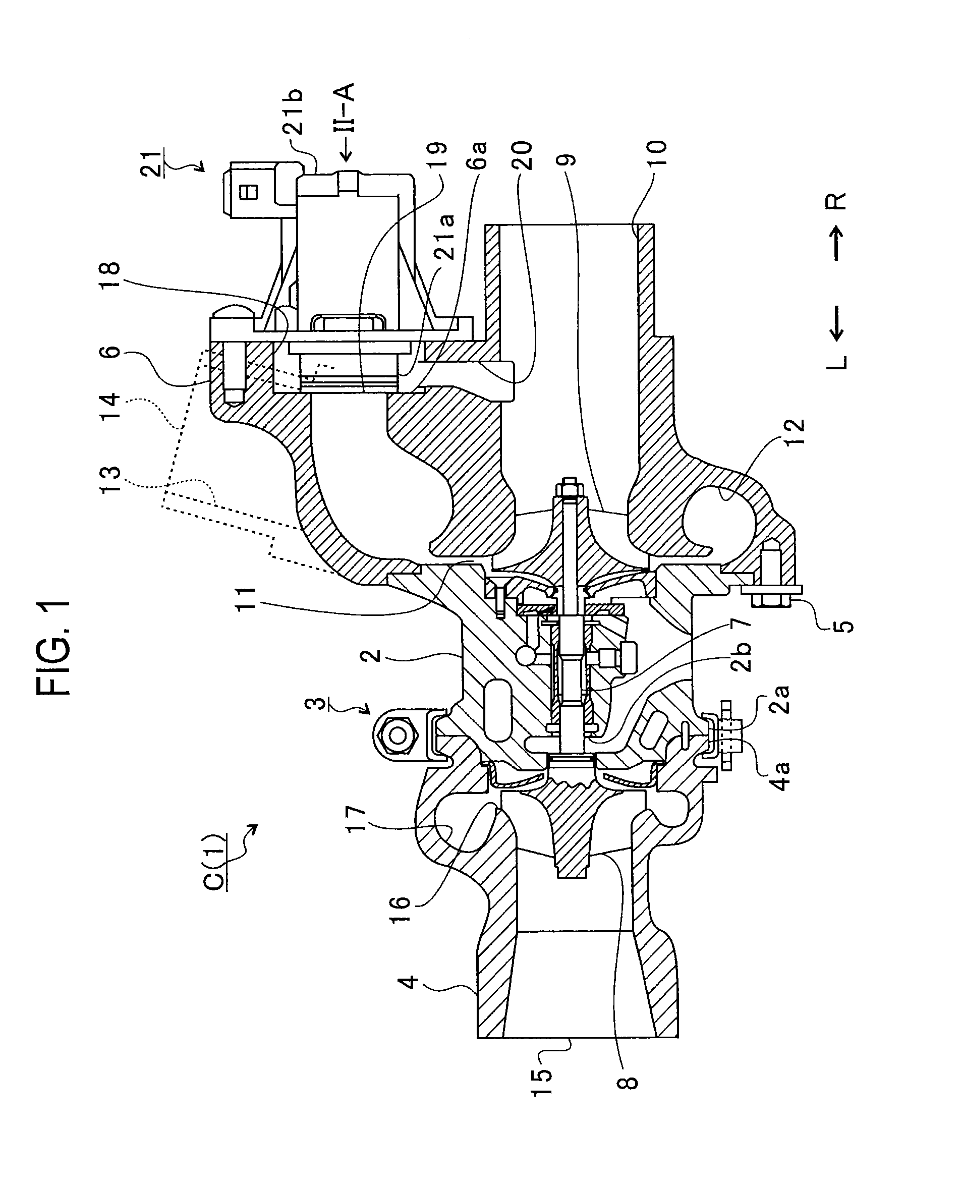
[0015]FIG. 1 is a schematic cross-sectional view of a turbocharger C. The following descriptions will be provided on the assumption that a direction indicated with an arrow L in FIG. 1 is a left side of the turbocharger C while a direction indicated with an arrow R therein is a right side of the turbocharger C. As shown in FI...


PUM


Abstract

A turbocharger includes: a suction passage into which a fluid is sucked from outside of a compressor housing; an outlet passage that guides the fluid, which is sucked through the suction passage and compressed, to the outside of the compressor housing; an opening portion formed in a wall surface of the compressor housing and serving as an opening of the suction passage; a return passage which makes the outlet passage and the suction passage communicate with each other through the opening portion, thereby returning the compressed fluid from the outlet passage to the suction passage; and an air bypass valve which opens and closes the opening portion. A level of a bottom surface of the return passage located on a vertically lower side therein declines from the outlet passage toward the suction passage without ever rising.

Description

BACKGROUND OF THE INVENTION[0001]1. Field of the Invention[0002]The present invention relates to a turbocharger including a compressor housing which is provided with a return passage for returning part of compressed air to an upstream side.[0003]2. Description of the Related Art[0004]There has been known a turbocharger including a bearing housing configured to rotatably hold a turbine shaft that is provided with a turbine wheel (turbine impeller) on one end and a compressor wheel (compressor impeller) provided on the other end. The turbocharger is connected to an engine and the turbine wheel is rotated by exhaust gas discharged from the engine. The rotation of the turbine wheel rotates the compressor wheel via the turbine shaft.[0005]The turbocharger compresses air with the rotation of the compressor wheel and sends the compressed air to the engine. In a vehicle or the like equipped with a turbocharger, when throttle valves in the engine are closed for deceleration, a boost pressure...

Claims


Application Information

Patent Timeline
IPC IPC(8): F04D27/00
CPCF04D27/0215F02M26/06F01D17/105F01D17/165F02B37/16F02C6/12F01D9/026F04D27/009
Inventor ISONO, YUUSUKEIWATA, KAZUAKIMORI, ATSUSHI
Owner IHI CORP
Learn More