
Vent cap for battery

a storage battery and vent cap technology, which is applied in the manufacture of cell components, cell component details, final product manufacturing, etc., can solve the problems of troublesome job, deterioration of battery performance, and risk of exploding a case of the battery, so as to prevent electrolyte solution leakage, improve the cycle life of the storage battery, and reliably opera

Inactive Publication Date: 2014-05-22
UNICK
View PDF3 Cites 21 Cited by
  • Summary
  • Abstract
  • Description
  • Claims
  • Application Information

AI Technical Summary

Benefits of technology

The present invention provides a storage-battery vent cap that can improve the life of a storage battery by blocking leakage of electrolyte solution, quickly exhausting gas and operating a valve at an appropriate range of pressure. The vent cap has a simple structure and a strong coupling strength of constituent elements, which simplifies the manufacturing process. The valve is elastically deformed according to the internal pressure of the storage battery to open or close the air vent, preventing leakage of electrolyte solution in a normal state. The valve can be operated quickly to exhaust gas and improve the cycle-life of the storage battery. The vent cap has a small possibility of breakdown, reduces production cost, and simplifies assembly of constituent elements. The insert and valve are coupled together through a coupling hole and fixing protrusion, and the body and insert are coupled together through a coupling groove and protrusion, ensuring a strong coupling strength of the constituent elements.

Problems solved by technology

However, since water of the electrolyte solution is decomposed deteriorating performance of the battery, the lead storage battery needs periodic water supplement, which is a troublesome job.
This increase of pressure caused by the generated gases not only deteriorates performance of the battery but also involves the risk of exploding a case of the battery.

Method used


Image

  • Vent cap for battery
  • Vent cap for battery
  • Vent cap for battery

Examples


Embodiment Construction

[0027]An exemplary embodiment of the present invention will be described in detail with reference to the accompanying drawings. In assigning reference numerals to respective constituent elements in the drawings, the same reference numerals designate the same constituent elements although the constituent elements are shown in different drawings.

[0028]In accordance with an exemplary embodiment of the present invention, a storage-battery vent cap (hereinafter, simply referred to as vent cap) 1 is a device installed in a vent hole 510 of a storage battery 500 to adjust an internal pressure of the storage battery 500 by exhausting a gas generated inside the storage battery 500 and by blocking inflow of external air (see FIG. 5)

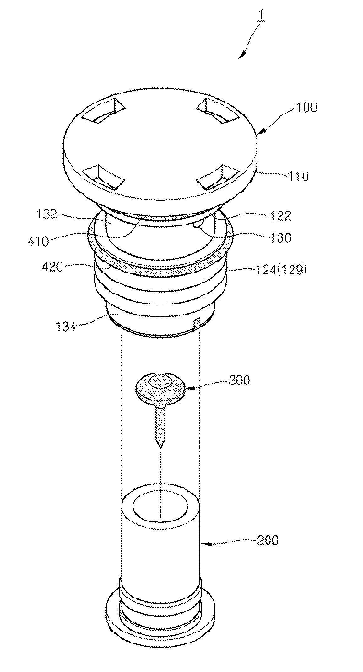
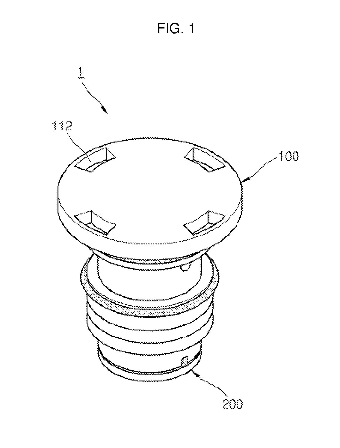
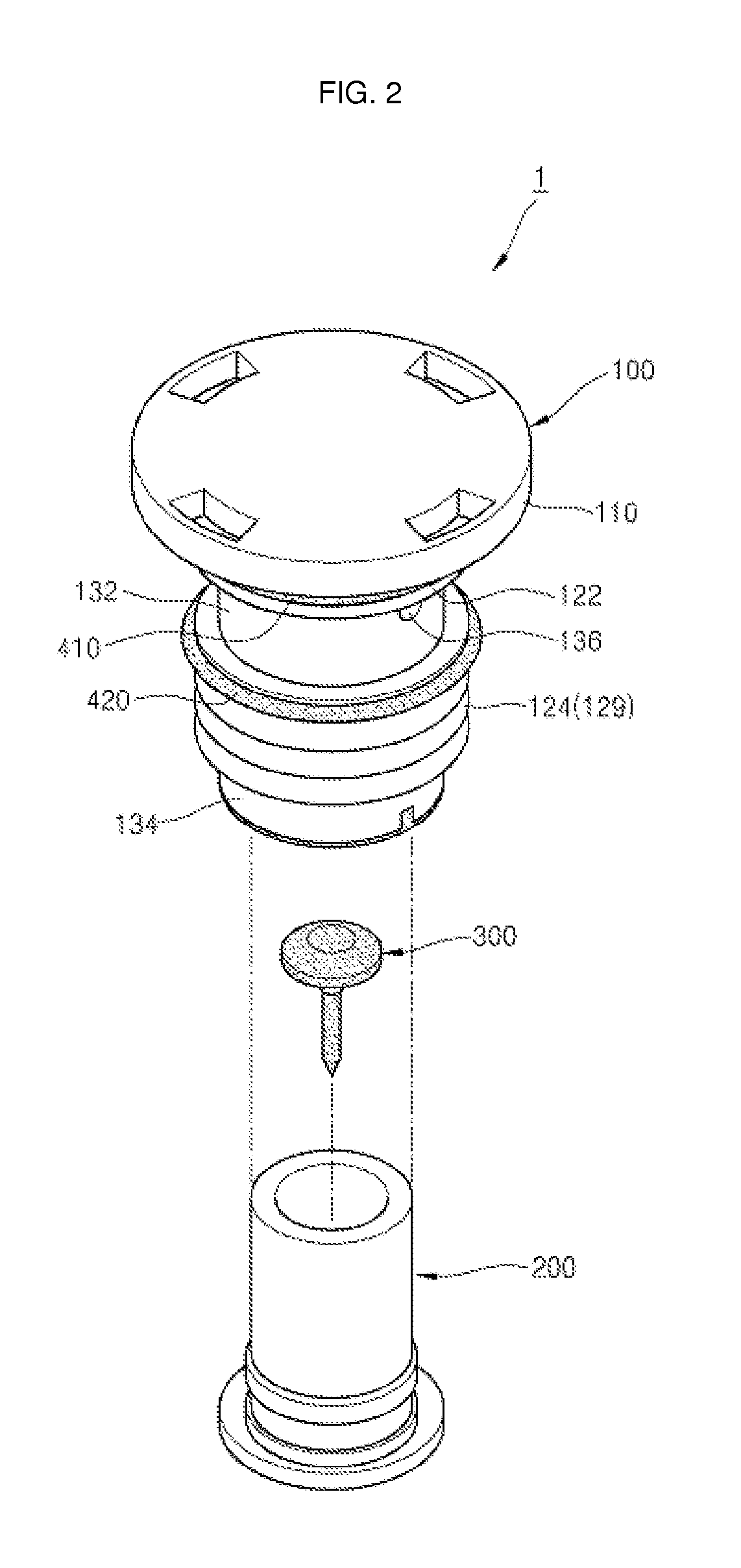
[0029]As shown in FIG. 1 and FIG. 2, the vent cap 1 includes a body 100, an insert 200 installed inside the body 100, and a valve 300 fixed to the insert 200. The vent cap 1 having such a structure has a small possibility of breakdown and a reliable operation since...


PUM

PropertyMeasurementUnit
internal pressureaaaaaaaaaa
pressureaaaaaaaaaa
internal pressureaaaaaaaaaa

Abstract

The present invention relates to a storage-battery vent cap which adjusts an internal pressure of a storage battery by exhausting a gas generated inside the storage battery to the outside and blocking inflow of external air. The vent cap includes a cylindrical body installed in a vent hole of the battery and formed with an exhaust hole; a cylindrical insert coupled to the body, a partition being formed inside the insert and a coupling hole and a air vent being formed in the partition; and a valve fixed to the coupling hole and elastically deformed by an internal pressure of the battery to open the air vent. The valve has an umbrella-like shape including a valve body having a larger diameter than that of the coupling hole, a cover formed on an outer circumferential surface of the valve body, and a fixing portion downwardly protruded from the valve body.

Description

CROSS-REFERENCE TO RELATED APPLICATION[0001]This application claims priority to and the benefit of Korean Patent Application No. 10-201 2-01 30323 filed in the Korean Intellectual Property Office on Nov. 16, 2012, the entire contents of which are incorporated herein by reference.BACKGROUND[0002]1. Field of the Invention[0003]The present invention relates to a vent cap for a storage battery, and in particular, it relates to a vent cap for a storage battery (or referred to as a storage-battery vent cap), which adjusts an internal pressure of the storage battery by exhausting a gas generated inside the storage battery to the outside and blocking inflow of external air.[0004]2. Description of the Related Art[0005]A lead storage battery is a rechargeable battery which can be repeatedly charged and discharged by an oxidation-reduction reaction generated between sulfuric acid serving as electrolyte and two plates formed of lead and lead oxide. The lead storage battery typically includes a ...

Claims


Application Information

Patent Timeline
Patent Type & Authority Applications(United States)
IPC IPC(8): H01M2/12
CPCH01M2/1229H01M2/1205Y02E60/10H01M50/308H01M50/325Y02P70/50H01M10/121H01M50/317
Inventor LEE, CHANG HOONMOON, KUK CHANKIM, CHUL HOLEE, KYUNG MIN
Owner UNICK
Learn More