Method and system for DLCO quality control testing

a quality control and equipment technology, applied in the field of quality control of dlco equipment, can solve the problems of large and expensive dual-syringe devices of sub-simulators, co and tracer gas detectors have similar responses (but not necessarily accurate or linear), and achieve the effect of lung volum

Active Publication Date: 2014-05-22
KOKO IT LLC
View PDF5 Cites 3 Cited by
  • Summary
  • Abstract
  • Description
  • Claims
  • Application Information

AI Technical Summary

Benefits of technology

[0044]Due to diffusion across the alveolar-capillary membrane, the ratio of alveolar CO concentration to inhaled CO concentration is lower than the corresponding ratio for the tracer gas. The effect of diffusion on alveolar CO concen

Problems solved by technology

Current DLCO simulators require large and expensive dual-syringe devices.
This procedure checks the inhaled volume accuracy in the DLCO test mode, which may be in error when spirometry measurements are not.
Current DLCO testing devices and practices suffer from several deficiencies and disadvantages.
It may also demonstrate that the CO and tracer gas detectors have similar response (but not necessarily accurate or linear) over a narrow range of gas concentrations.
There are a number of challenges and disadvantages in using the Hans Rudolph simulator.
First, the procedure is complex and prone to errors.
Difficulties arise from a significant certainty that the syringe is properly purged of any previously used gas mixtures.
If precise timing of the operation of the 3-liter syringe is not maintained the test of the DLCO equipment is invalid and the test must be re-performed, resulting in increased costs for the precise gas mixtures used in the testing or even improper calibration of the DLCO equipment based on faulty test results.
Switching alveolar gas bottles adds to the complexity and cumbersomeness of simulator

Method used


Image

  • Method and system for DLCO quality control testing
  • Method and system for DLCO quality control testing
  • Method and system for DLCO quality control testing

Examples


Embodiment Construction

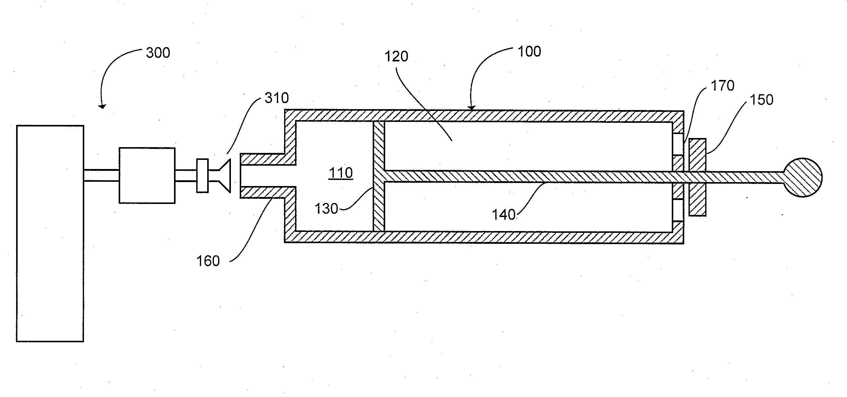
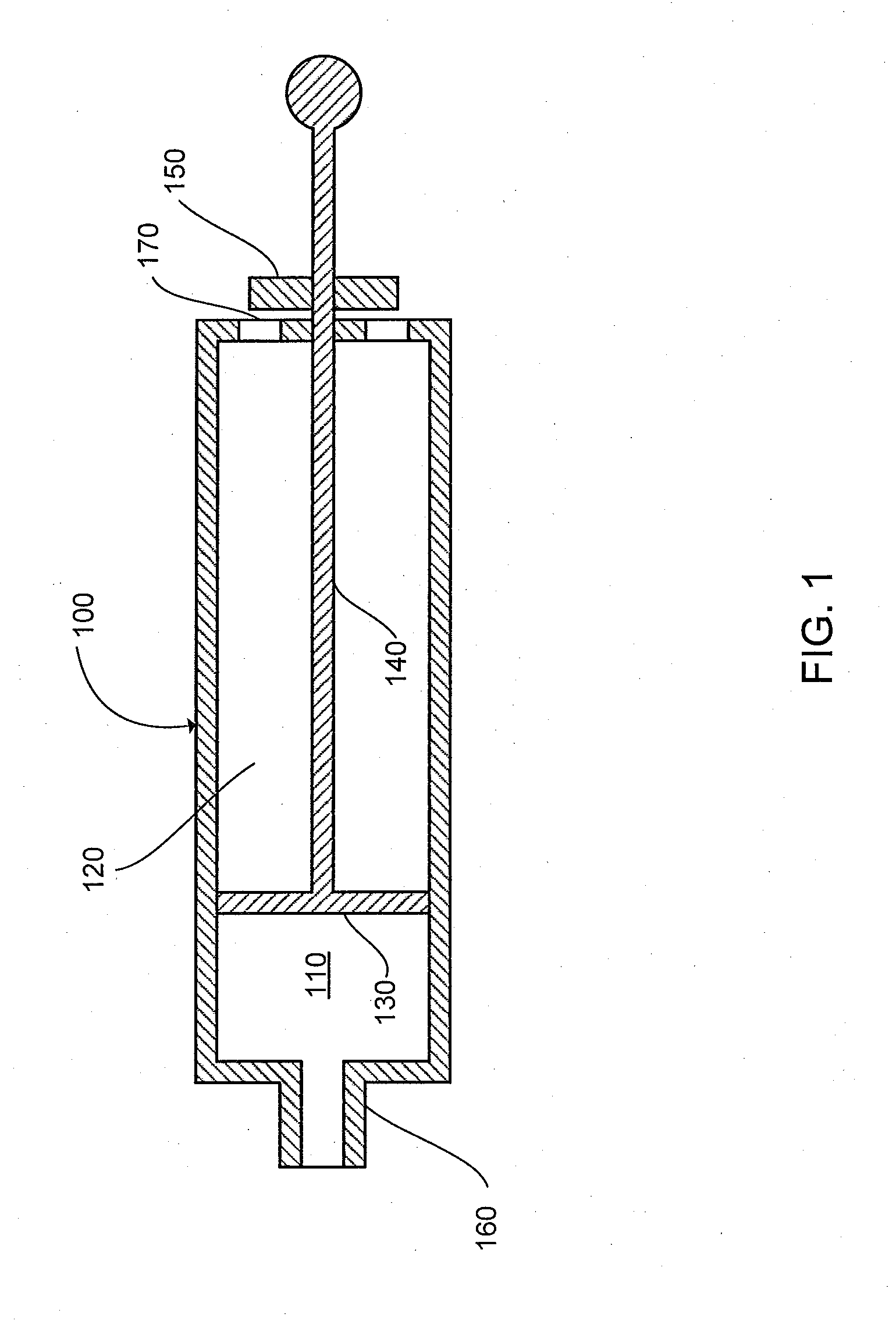
[0063]Referring now to the drawings, where like or similar elements are designated with identical reference numerals throughout the several views, and referring in particular to FIG. 1, it illustrates the cross-section of an embodiment of a single-syringe simulator quality control device 100. The simulator syringe 100 has an inactive space 110 and a stroke volume 120 and can be a curvilinear or non-curvilinear cylinder. In a preferred embodiment, the maximum stroke volume is 6 liters or greater. Such a volume is most beneficial to simulate the inspired volumes associated with large adults. The volume of the inactive space 110 can be adjusted by moving the piston 130 either forward or back. The volume of the inactive space 110 starts from a predetermined volume. In other words, the piston 130 starts from a predetermined position. The predetermined volume can be set by a collar 150 situated on the shaft 140 of the piston 130 outside the body of the simulator syringe 100. In some embod...


PUM


Abstract

The present invention can provide a system and method for DLCO quality control testing and can include an apparatus for testing a pulmonary diagnostic device capable of performing single breath carbon monoxide uptake measurement, comprising: a single gas-tight chamber, with a gas port configured to receive gas from or to expel gas to the exterior of the chamber and a partition configured to change the volume of the single gas-tight chamber; the single gas-tight chamber capable of expanding and contracting; a member disposed within the single gas-tight chamber and configured to limit the movement of the partition, the member being adjustable to set a predetermined maximum volume of the single gas-tight chamber and a predetermined volume of DLCO test gas that the single gas-tight chamber can receive; and an interface configured for the transfer of gas between the pulmonary diagnostic device and the simulation device via the gas port.

Description

COPYRIGHT[0001]A portion of the disclosure of this patent document contains material that is subject to copyright protection. The copyright owner has no objection to the facsimile reproduction by anyone of the patent disclosure, as it appears in the Patent and Trademark Office patent files or records, but otherwise reserves all copyright rights whatsoever.FIELD OF THE INVENTION[0002]The present invention relates to quality control of DLCO equipment. In particular, but not by way of limitation, the present invention relates to systems and methods for ensuring the measurement accuracy of pulmonary testing devices used for single-breath determination of carbon monoxide uptake in the lung.BACKGROUND OF THE INVENTION[0003]Current DLCO simulators require large and expensive dual-syringe devices. For example, the Hans Rudolph DLCO simulator, as described in U.S. Pat. No. 6,415,642 requires two syringes (3 and 5 liters) that are joined by a manifold via a three-way valve. The manifold is co...

Claims


Application Information

Patent Timeline
IPC IPC(8): A61B5/08
CPCA61B5/082A61B5/0813A61B5/097G01N33/497
Inventor CHU, EDMONDNORGARD, ERICWALLACE, WILLIAM CHASE
Owner KOKO IT LLC
Why Eureka
Try Eureka