Coordinate measuring apparatus for measuring a workpiece

a technology for workpieces and measuring apparatuses, applied in the direction of measurement devices, instruments, and error compensation/elimination, etc., can solve the problems of large measurement errors, deformation of the mechanism of the coordinate measuring apparatus, and deformation of the measuring apparatus, etc., to achieve high degree of rigidity, high precision, and high degree of precision

Active Publication Date: 2014-05-29
CARL ZEISS IND MESSTECHN GMBH
View PDF11 Cites 3 Cited by
  • Summary
  • Abstract
  • Description
  • Claims
  • Application Information

AI Technical Summary

Benefits of technology

[0025]A stiff frame which is constructed in such a manner and in which the longitudinal members, the vertical supports and the cross members are stiffly connected to one another in the described manner has considerable advantages.
[0026]Although, by this means, firstly a coordinate measuring apparatus is created, the coordinate measuring apparatus being suitable for relatively large workpieces, such as, for example, car bodies, the advantage that the position of the horizontal guides is determined fairly accurately can thereby nevertheless be used. Since, namely, the frame can be manufactured very accurately, adjustment problems, as occur in the case of coordinate measuring apparatuses in which each vertical support has to be fastened separately, for example via dowels, on the floor, can thereby be avoided from the outset. Nevertheless, the frame can be transported in a highly space-saving manner to the customer by being dismantled into its individual parts (longitudinal member, cross members and the supports) and the...

Problems solved by technology

However, it is then problematic if the floor is deformed.
Such a deformation can take place, for example, due to sinking of the substructure or due to heavy workpieces.
This results in the mechanism of the coordinate measuring apparatus being deformed and considerable measurement errors occurring by this means.
However, they are suitable only for relatively small workpieces.
An enlargement of the coordinate measuring apparatuses to greater measuring volumes, with which even large workpieces can then be measured, ...

Method used


Image

  • Coordinate measuring apparatus for measuring a workpiece
  • Coordinate measuring apparatus for measuring a workpiece
  • Coordinate measuring apparatus for measuring a workpiece

Examples


Embodiment Construction

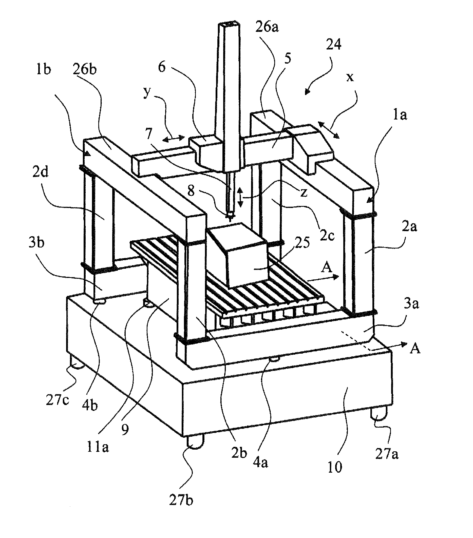
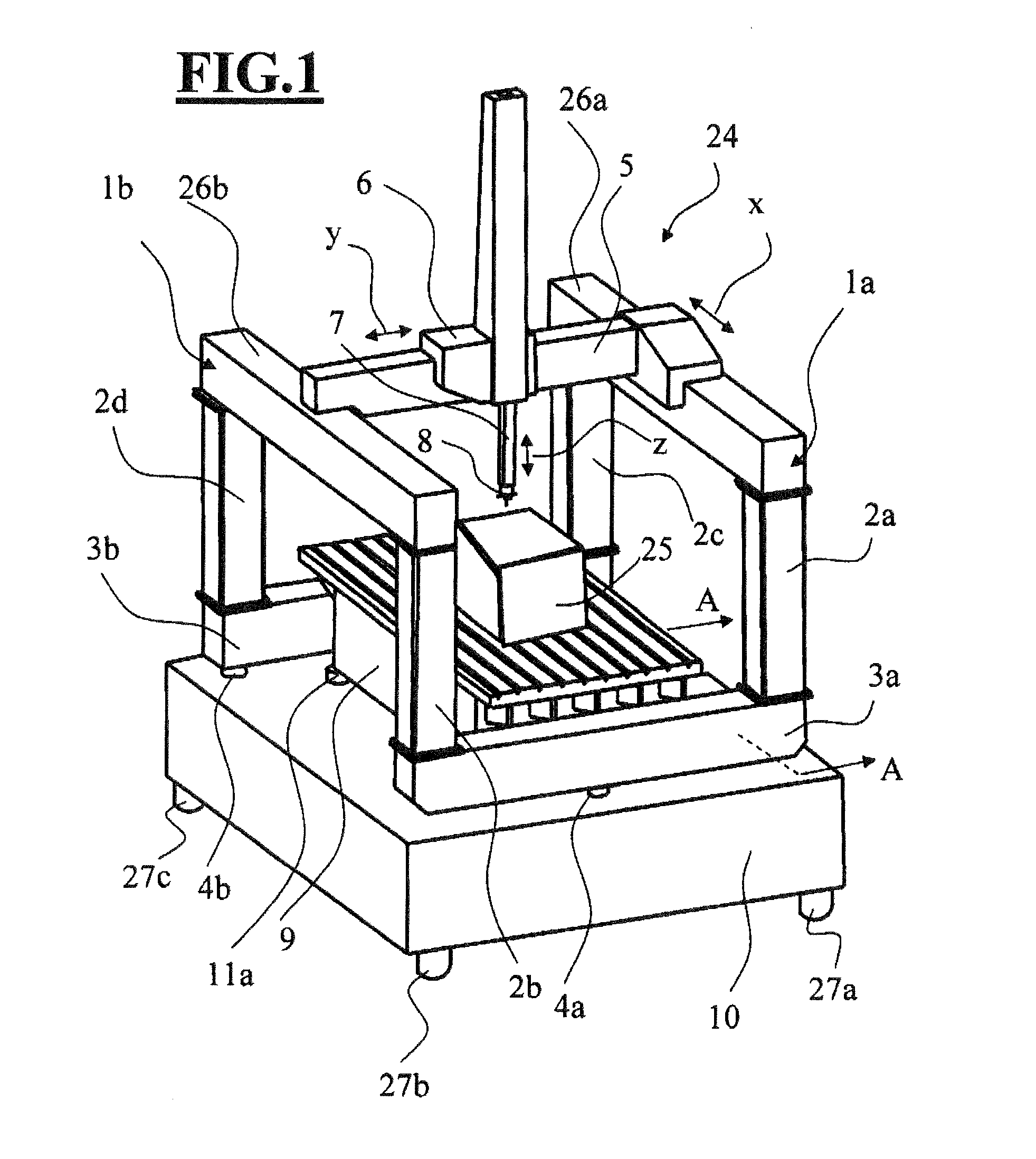
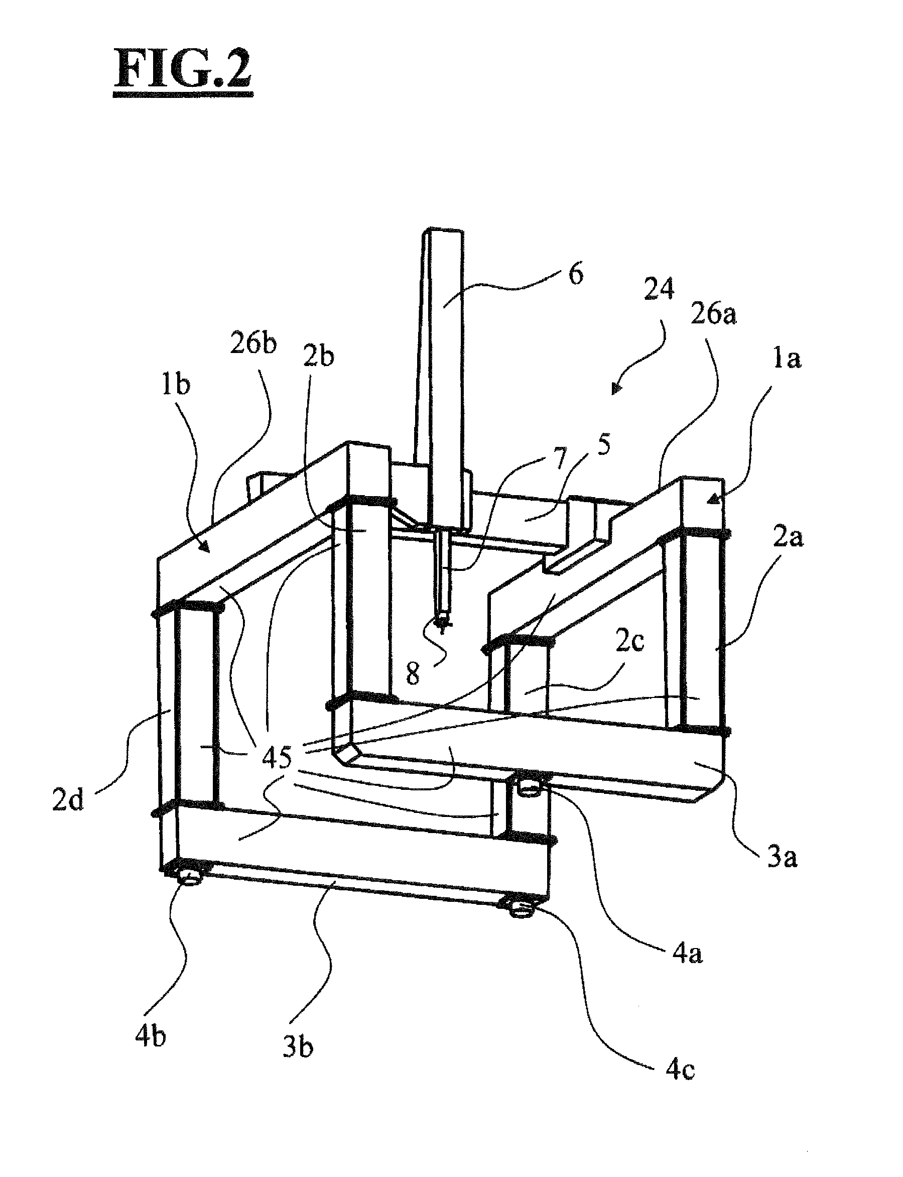
[0072]FIG. 1 shows, purely by way of example, a coordinate measuring apparatus, in which the invention is realized. FIG. 2 here shows some of the components which can be seen in FIG. 1, namely the mechanism 24, which is described in detail further below, in addition to the sensor 8 which is fastened thereto, in a perspective view laterally from below.

[0073]A coordinate measuring apparatus according to the invention will now be explained in more detail with reference to FIGS. 1 and 2, wherein the designations used in the claims, if required, are placed between parentheses after the expressions. In order to measure a workpiece 25 which is mounted here on a workpiece table 9, a sensor 8 can be moved relative to the workpiece 25 in the three coordinate directions x, y and z which are perpendicular to one another by means of a mechanism 24. The respective coordinate directions in this case are illustrated by arrows x, y and z. The sensor 8 here can be configured, for example, so as to be...


PUM


Abstract

A coordinate measuring apparatus for measuring a workpiece having a workpiece surface includes a sensor to capture the workpiece surface and a mechanism to move the sensor in coordinate directions (x, y, z) relative to the workpiece. The mechanism includes a rigid frame, a mount and measuring skids. The rigid frame includes mutually parallel horizontal longitudinal members having respective horizontal guides. The rigid frame includes vertical supports having respective upper and lower ends. The horizontal longitudinal members are rigidly connected to the upper ends of the vertical supports. The rigid frame includes transverse members oriented transverse to the longitudinal members and being rigidly connected to the lower end of the vertical supports. The transverse members are supported via the mount and a first one of the measuring skids is configured to move the sensor in the coordinate direction (x) along the first and second horizontal guides.

Description

CROSS REFERENCE TO RELATED APPLICATIONS[0001]This application is a continuation application of international patent application PCT / EP2011 / 063384, filed Aug. 3, 2011, designating the United States, and the entire content of this application is incorporated herein by reference.FIELD OF THE INVENTION[0002]The invention relates to a coordinate measuring apparatus for measuring a workpiece. The apparatus includes:[0003]a) a sensor for detecting the workpiece surface of the workpiece,[0004]b) a mechanism for moving the sensor relative to the workpiece in one or more coordinate directions (x, y, z), wherein the mechanism, in turn, includes the following:[0005]a first horizontal longitudinal member with a first horizontal guide,[0006]a second horizontal longitudinal member with a second horizontal guide which is oriented parallel to and spaced apart from the first horizontal guide,[0007]at least one first vertical support and a second vertical support, wherein the first horizontal longitud...

Claims


Application Information

Patent Timeline
IPC IPC(8): G01B5/008
CPCG01B5/008G01B5/0014
Inventor MATZKOVITS, BERTHOLD
Owner CARL ZEISS IND MESSTECHN GMBH
Why Eureka
Try Eureka