Transmission and electric vehicle comprising same

Inactive Publication Date: 2014-05-29
AICHI MASCH IND CO LTD
View PDF12 Cites 2 Cited by
  • Summary
  • Abstract
  • Description
  • Claims
  • Application Information

AI Technical Summary

Benefits of technology

[0020]With the electric vehicle of the present invention, including the transmission device of the present invention of the mode described above, it is possible to exhibit the effects exhibited by the transmission device of the present invention, e.g., the ability to output the re

Problems solved by technology

However, the transmission device disclosed in Japanese Laid-Open Utility Model Publication No. 1-146044 suffers from shortcomings such as the inability to fully ensure the speed reduction ratio nee

Method used


Image

  • Transmission and electric vehicle comprising same
  • Transmission and electric vehicle comprising same
  • Transmission and electric vehicle comprising same

Examples


Example

Embodiment 1

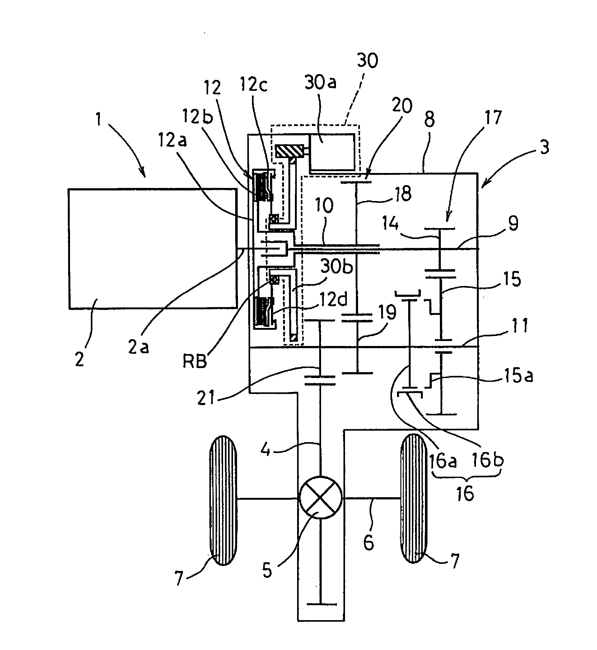
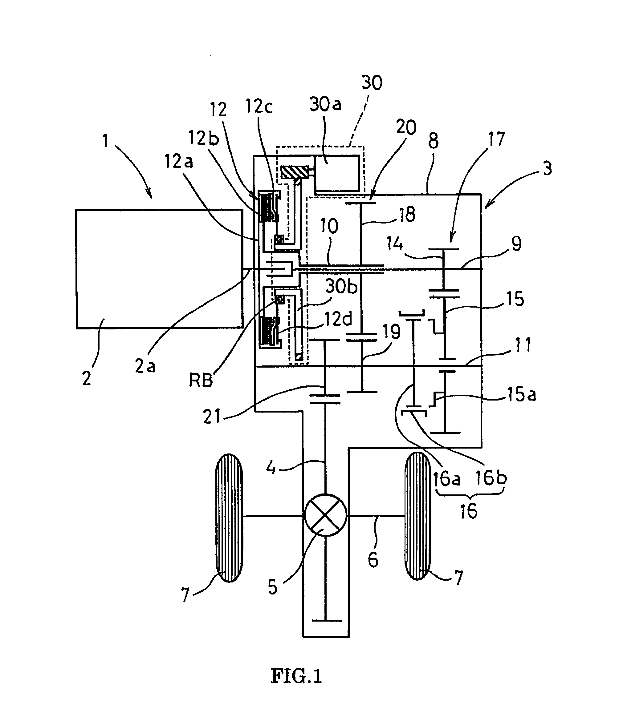
[0024]FIG. 1 is an arrangement and configuration schematic view of an electric vehicle provided with a gear transmission device for achieving a two-stage transmission for low speed and high speed.

[0025]An electric vehicle 1 is provided with: a motor 2, which is a power source; a transmission device 3 for shifting the power coming from the motor 2 to two stages for low speed and high speed; a differential device 5 that is connected to the transmission device 3 and transmits the power coming from the transmission device 3 to an axle 6; and wheels 7 that are rotated by the power sent to the axle 6.

[0026]The transmission device 3 has input shafts9, 10 and an output shaft 11 that are rotatably arranged in parallel within a case 8, and a ring gear 4 of the differential device 4 is in meshed engagement with an output gear 21 fixed to the output shaft 11.

[0027]The input shafts are constituted of a low-side input shaft 9 and a high-side input shaft 10 that is arranged coaxially w...

Example

Embodiment 2

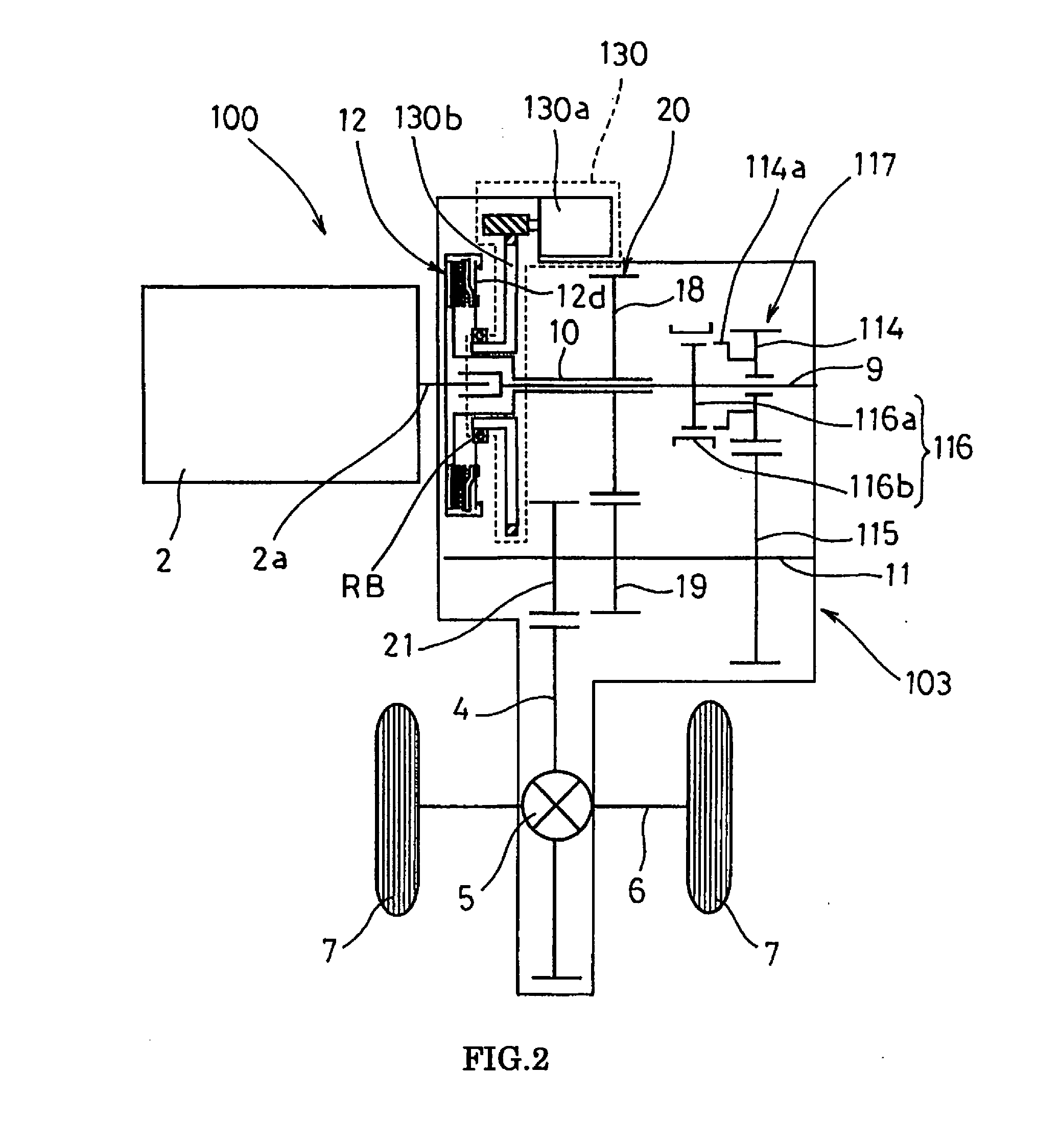
[0051]An electric vehicle 100 equipped with a transmission device 103 of a second embodiment of the present invention shall next be described.

[0052]FIG. 2 is a schematic configuration diagram of the electric vehicle equipped with the transmission device 103 of the second embodiment.

[0053]The electric vehicle 100 of the transmission device 103 of the second embodiment is given the same configuration as that of the electric vehicle 1 provided with the transmission device 3 of the first embodiment, except in that the low-side gear mechanism 17 is changed to a low-side gear mechanism 117, and in that the synchro mechanism 16 is changed to a synchro mechanism 116. As such, like reference numerals are assigned to parts of the electric vehicle 100 of the second embodiment that are of like configuration to that of the electric vehicle 1 of the first embodiment, and a description thereof is omitted.

Example

[0054]In the transmission device 103 of the second embodiment, as is depicted, a driving low gear 114 is idly arranged on the low-side input shaft 9 and a driven low gear 115 is fixed onto the output shaft 11; on the low-side input shaft 9, the synchro mechanism 116 is disposed adjacently on the left-hand side depicted of the driving low gear 114.

[0055]A clutch gear 114a is fixedly provided to the driving low gear 114, and moving a sleeve 116b of the synchro mechanism 16 to the right-hand side depicted causes the clutch gear 114a and a hub 116a of the synchro mechanism 116 to become engaged with each other via the sleeve 116b. This fixes the driving low gear 114 to the low-side input shaft 9 and achieves the low-speed stage.

[0056]According to the transmission device 103 of the second embodiment described above, the effects are similar to those of the transmission device 3 of the first embodiment, i.e., it is readily possible to ensure a configuration by which the power required can ...


PUM


Abstract

A transmission device includes an output shaft, first and second input shafts, a first gear mechanism, a selective fixing device and a connecting and disconnecting device. The second input shaft is coaxially arranged on an outside periphery of the first input shaft. The first gear mechanism couples the first input shaft and the output shaft with a first gear ratio. The first gear mechanism includes an idle gear mounted on one of the first input shaft and the output shaft. The selective fixing device selectively fixes the idle gear to one of the first input shaft and the output shaft. The second gear mechanism couples the second input shaft and the output shaft with a second gear ratio. The connecting and disconnecting device selectively connects and disconnects the second input shaft to the rotating shaft.

Description

CROSS-REFERENCE TO RELATED APPLICATIONS[0001]This application is a U.S. National Stage of International Application No. PCT / JP2011 / 078503, filed Feb. 12, 2011.BACKGROUND[0002]1. Field of the Invention[0003]The present invention relates to a transmission device for achieving a two-speed transmission for low-speed and high-speed, and an electric vehicle comprising same.[0004]2. Background Information[0005]A conventional transmission device is disclosed in Japanese Laid-Open Utility Model Publication No. 1-146044. In this patent publication, the transmission device, is provided with a low gear supported on an output shaft via a one-way clutch and a high gear that is freely rotatable on the output shaft. The high gear is arranged so as to be selectively fixed to the output shaft by a synchro mechanism. The transmission device automatically achieves a low-speed stage on the basis of the relative rotation between the low gear and the output shaft, and achieves a high-speed stage by fixati...

Claims


Application Information

Patent Timeline
IPC IPC(8): F16H3/02B60L50/16
CPCB60L50/16F16H3/089F16H2200/0021F16H2200/0034Y02T10/7072B60K1/00B60L2240/12B60L2240/486B60L2240/507B60L2270/145Y02T10/72Y10T74/19251F16H3/02Y02T10/70
Inventor KAMINAGA, SEIJI
Owner AICHI MASCH IND CO LTD
Why Eureka
Try Eureka